Approaching Final Form

Over the last few days I have put several hours into development of the main chassis structures. Between the two main parts several needs have to be met including:

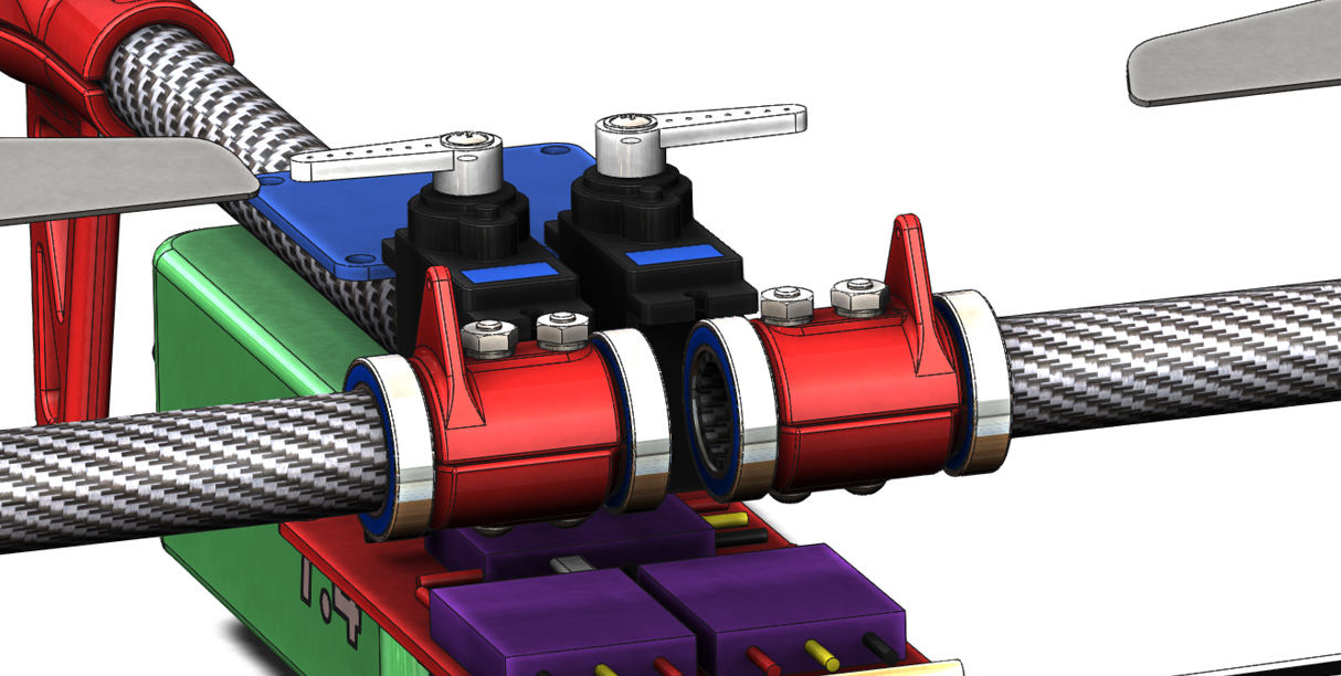
  • Supporting the front arm bearings and the associated loading
  • Mounting the flight controller
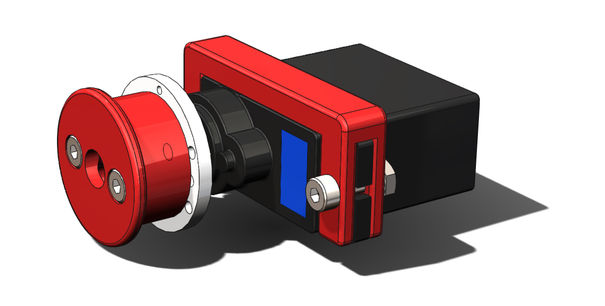
  • Supporting the servos in an adjustable manner (for belt tension)
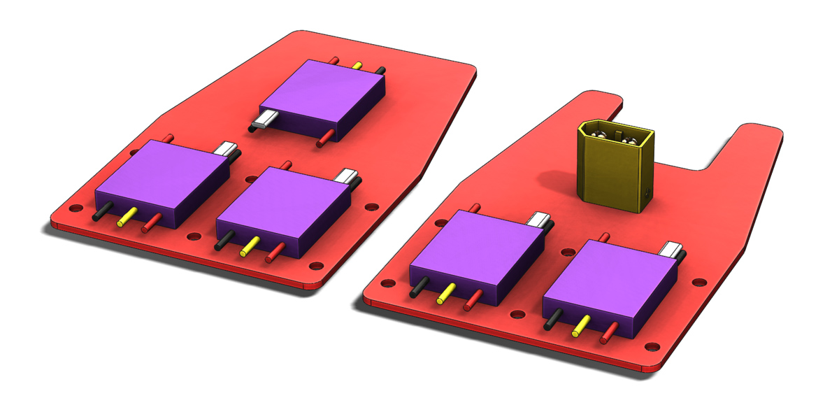
  • Fitting between the power distribution plates and around all the moving components
  • Attaching the rear boom

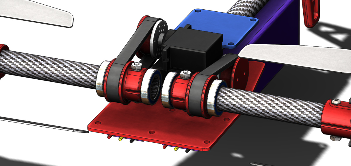
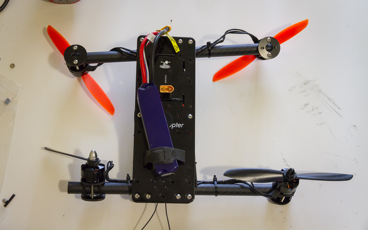
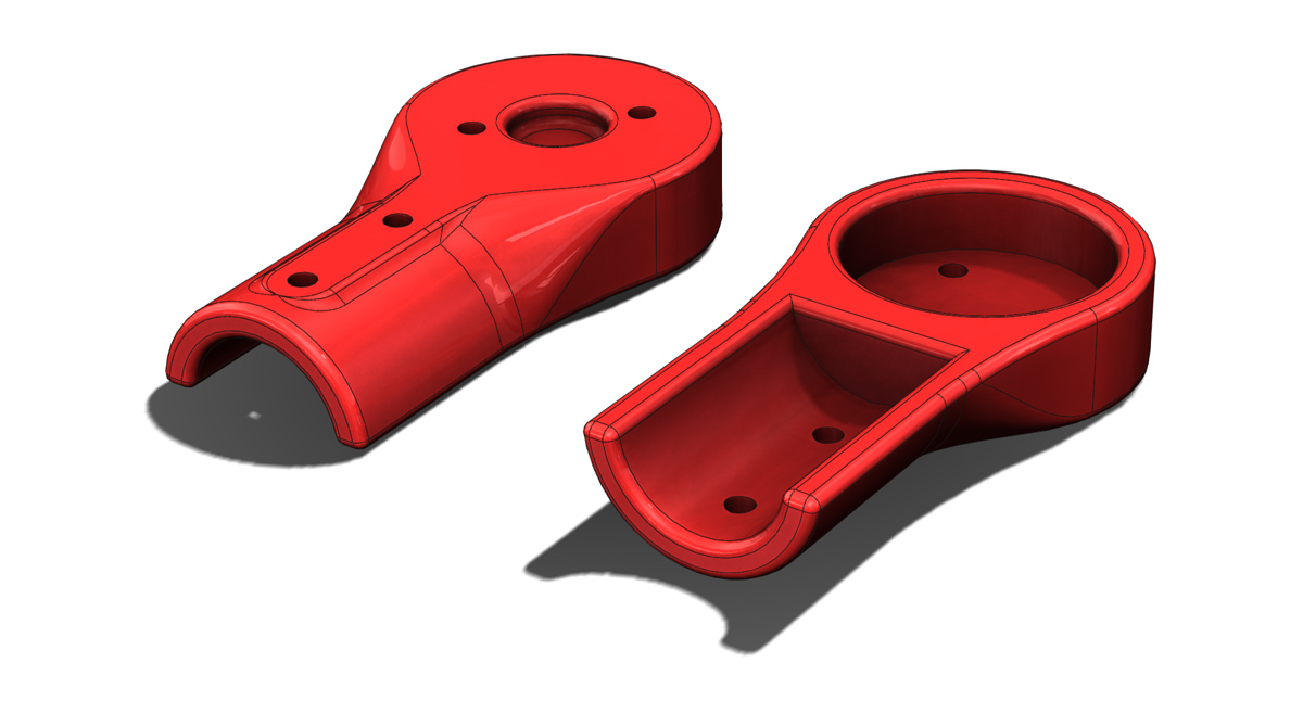
So far as seen in the image below the external shape is mostly in place. Internally the bearing support area is mostly sorted out but the servo mounting is not. As such I will hold on images of internal detail until that is in a ‘working’ state.

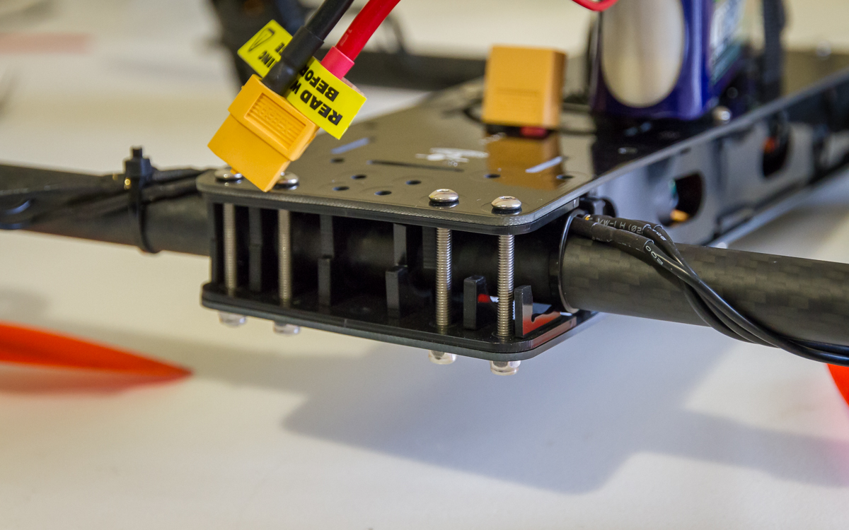
Also visible in the image is the rear boom clamping. A slotted hole penetrates the rear of the bottom chassis structure which is then clamped through the two holes in the side. Currently the supporting structure around this area is very deep so the clamping may not be particularly effective (i.e. structure may be to stiff), I will need to reassess.

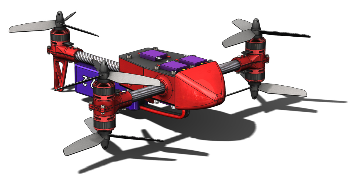
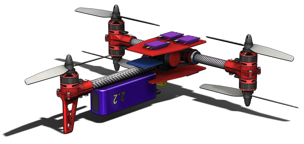
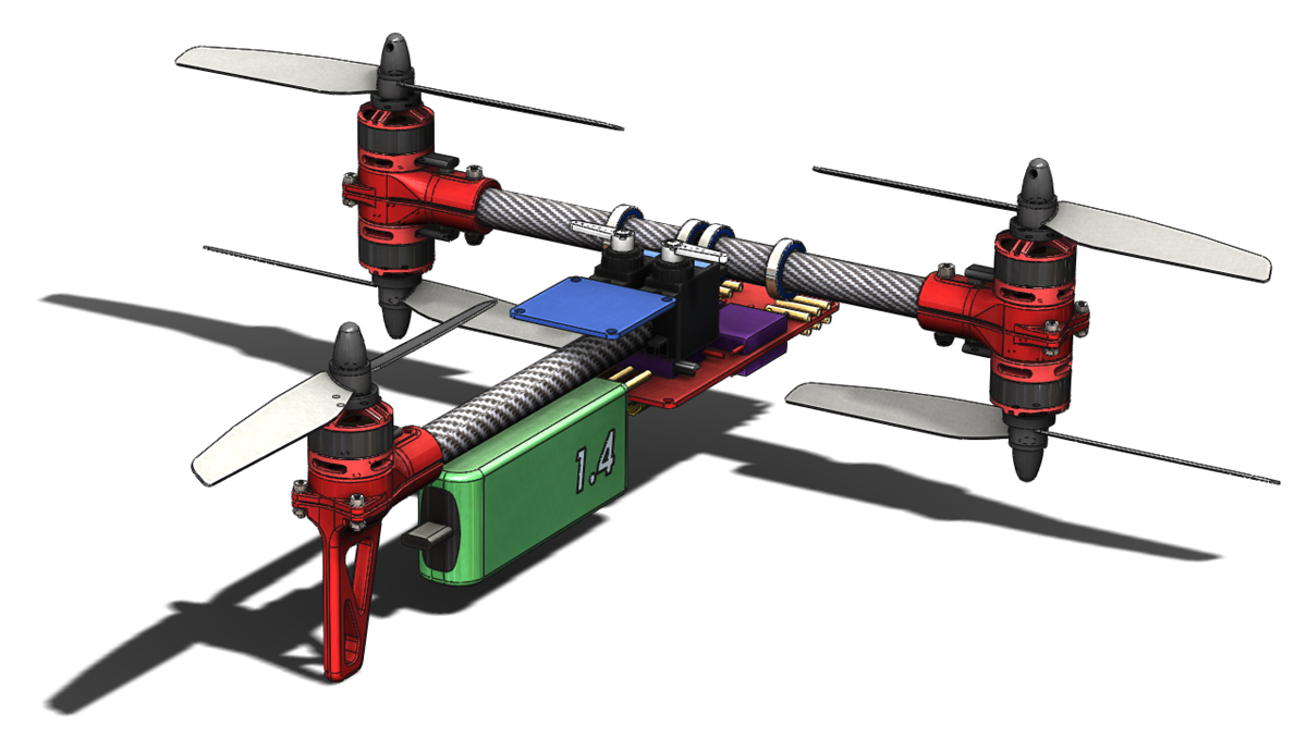
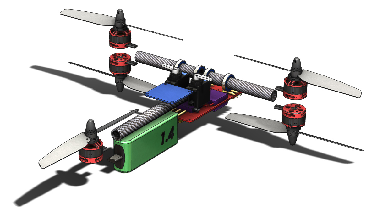
There is further external detail to work out around the flight controller mounting and battery. You may also note that I have changed the propellers. Crucially to a 5″ diameter but also shown here with 3 blades. The data I have seen suggests that a 5×4 propellor provides similar thrust to a 6×3 propellor (at the expense of some efficiency) and my experience with 5×4 props on the Spidex 220 has made me happy to consider this an alternative. I have not yet reduced the frame size so a 6″ propellor is still an option.

MC2 020

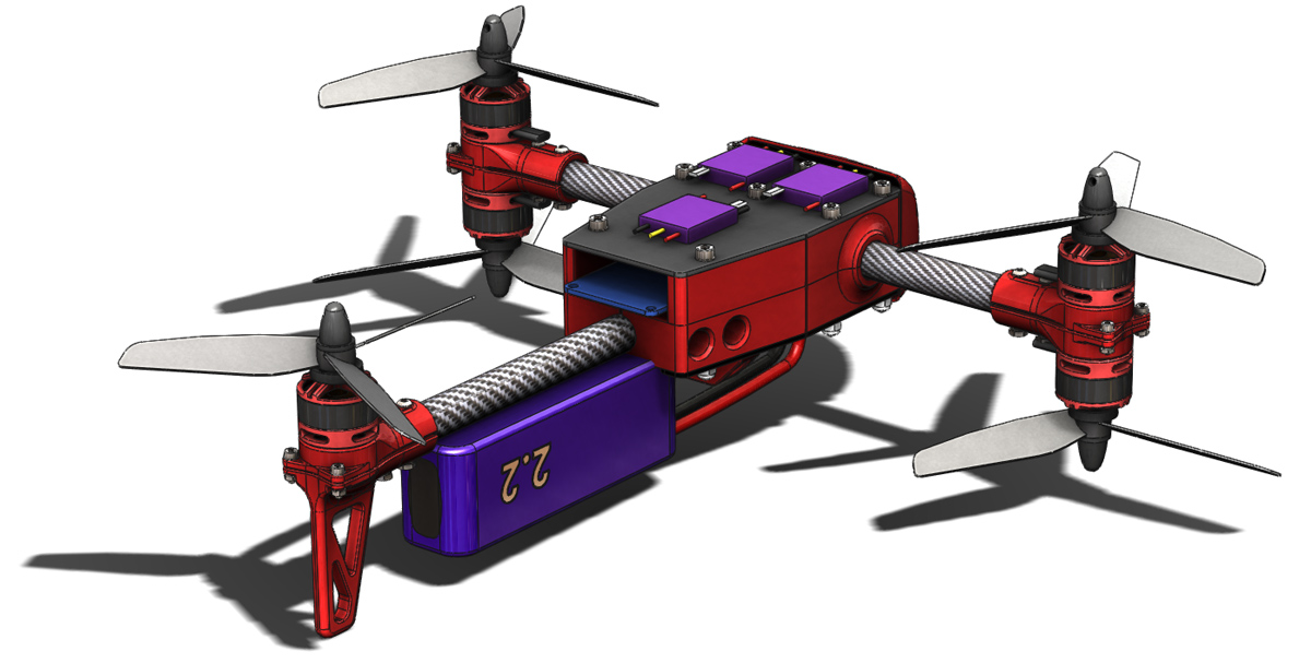
Also added is a front nose cone, primarily for aesthetic reasons at this point but it will surely improve the aerodynamics somewhat too. It is currently only a hollow place holder. The intention is to make it a snap fit on to the front of the chassis structures. That will be another learning experience and experiment in 3D printing to go along with everything else experimental on this airframe.

MC2 021

To facilitate the adjustment of the belt tension I have added a slider carriage of sorts to the servos which will fit into slots on the chassis structures. I’ve yet to add the tooth detail to the pulleys for 3D printing.

MC2 023

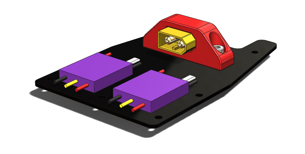
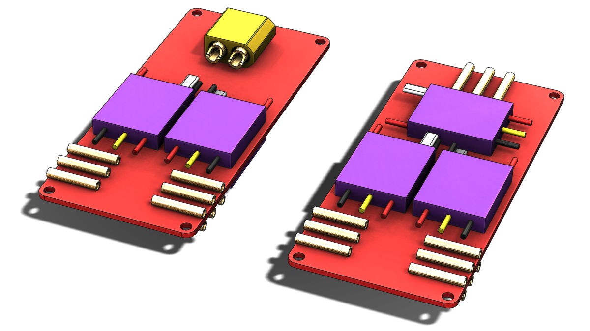
The final little detail to show off today is a holder for an XT60 socket. I decided that having the connector flat will mean less wire hanging low off the bottom of the craft.

MC2 022

Boom Control Belts

After looking at the range of motion that was going to be achievable with the previously shown boom control arms I was dissatisfied. Only about 70° was realistic. As a rough goal I would like to achieve 135° (90° forward and 45° backward). To get this range of motion and maintain a compact envelope I have decided to investigate the use of a belt drive system. Shown below is the layout I have come up with. The servos are laid on their side and stacked on top of each other and custom pulleys are used at both ends. It may be possible to source a pulley to fit the servo directly but at this stage I have not come across a source so I intend to pursue a 3D printed pulley attached to a standard round horn.

MC2 019

The power distribution philosophy has also seen some development. Primarily I have split the ESCs onto separate top and bottom boards. These boards will also serve as sandwich plates on the outsides of the internal structure (supporting bearings, servos etc.). I’ve also decided to forgo the use of board mounted bullet connectors and instead solder the motor wires either directly to the ESCs or onto the power distribution boards. I learnt from the construction of the Spidex 220 that this is really not as much of a complication as I had imagined it might be. The extra board real estate also opens up a good spot for the XT60 connector, the battery wire would loop around and in on itself to connect.

MC2 018

All together this creates a fairly tall stack height. As I develop the conceot further I hope to find ways to minimise it.

MC2 017

VersaCopter & Spidex 220 Rebuilt

After receiving my crash kits for the VersaCopter I have rebuilt it without any further drama. The only change made on the rebuild was to flip the orientation of the capacitors across the power input on the two ESC’s adjacent to the flight controller. They now rest back over the top of the ESC rather than poking out along the wires. As previously mentioned they were causing interference problems with the USB connector and various other connections on the flight controller. No such problems exist now.

Also rebuilt over the weekend was the Spidex 220, when I last flew that I took off aggressively thinking it was in angle mode when in fact it was in rate mode. Needless to say the quad flipped on its head and smashed in to the ground. Thankfully nothing beyond the propellers was actually broken but the force of the crash was enough to pull it to pieces so I thought a full workbench rebuild was a wise choice to ensure there wasn’t any hidden damage.

Now having them both built I could get a photo of them together for a size comparison.

s220-8

I also tried to get a buzzer working on the CC3D mini in the Spidex 220 whilst it was on the bench again but so far have not had success. The best way I have seen to achieve this is to move the buzzer output to motor channel 6 with a custom build of Cleanflight and a transistor to switch the buzzer. After having put everything in place as required it doesn’t work but I am unsure at the moment which piece of the puzzle is at fault. More investigation will be required. For now an external battery monitor on my new higher discharge rate batteries will suffice.

s220-9

Spidex 220

After coming across a great deal on most of the flight hardware for a Spidex 220 and realising I already had all the other required pieces to get it in the air I now have another mini quadcopter. For $130aud I got my hands on:

  • Spidex 220 frame kit
  • 4 Emax 12 amp speed controls
  • 4 DYS 1806 brushless motors
  • CC3D mini flight controller

To get it in the air I already had:

  • 1300mAh batteries (unfortunately of the 25C variety I have since discovered)
  • FrSky X4R receiver
  • 5040 propellers
  • Misc. bits and pieces (heat shrink tube, wire, connectors etc.)

As with the VersaCopter, at this stage i have built this up without any FPV or camera equipment, that’s an expense for the future.

s220-1

How to tackle power distribution and connection proved to be the biggest question of this build. Seen above is the solution I came up with which I think is really quite tidy. The rear two motors are joined together with another wire which travels forward to the power distribution board. In previous builds I have always been frustrated by the process of trying to solder multiple wires together, even two can be a frustrating experience. This time around I made a point of seeing how others tackled this problem and very quickly came across a wire wrapping method. The Flite Test crew illustrate it succinctly in the video below.

Using this method, and even splitting it  into two stages, I found the process much more agreeable. The +ve and -ve runs are mirrored with one up each side of the frame. A couple of holes were drilled into the base plate to hold zip ties in critical locations.

s220-3

The wires from the rear motors meet the battery wires and front motors at this small power distribution board made from a piece of strip board. The copper strips aren’t really carrying much of the power it simply provides an easy foundation onto which each wire can be joined. Also hinted at in the photo above is the fact that I have routed the battery wires through the base plate. This seemed the only tidy way I could route them whilst providing enough tension that the battery leads be pulled out of range of the propellers.

s220-7

The battery connector flies freely out the bottom of the craft but is pulled taught when a battery is connected.

s220-2

To fit the FrSky X4R receiver between the flight controller and the battery I striped it of its carboard housing and replaced it with heat shrink, using double sided tape it is then attached directly to the housing for the CC3D mini. For a tidy install I also shortened the wires from each ESC. On all but one connector the +5v wire is also removed and held back with a small loop of heat shrink. I have changed the software on the CC3D mini over to CleanFlight due to my familiarity with that. Installing it was quite simple using the OpenPilot bootloader and flashing software. In the future I would also change over to a CleanFlight bootloader as my experience with that on NAZE32 hardware is a little smoother.

s220-4

To fit the ESC’s in to the designated spots on the arms the outer corners of the ECS’s need to be trimmed slightly. A cut out in the cross member on the frame was also required to pass the signal wire from the bottom of the board. The motor wires are soldered directly to the ESC and by paying attention to which wire was going where I was able to get a pair of CCW rotating motors and a pair of CW rotating motors without having to rework the soldering.

s220-6

Initial flight impressions are a bit limited so far due to windy days but from what I have experienced it is a very punchy little rig. I am seeing some vibration induced instability/oscillation at hover which will need some work and the tuning could also do with a touch up. All in all though, a very fun little platform that I’ve picked up for minimal outlay.

VersaCopter – Crash Kit Required

Up until now I had managed to avoid inflicting any serious damage on the VersaCopter despite a couple of unexpected visits to the ground. The first time it came down was when I clipped a post, judging depth and plotting a course is tough when flying around obstacles! From that a couple of small cracks developed in the side plates but everything could still be straightened and flown again.
The second crash came when I fumbled the sticks whilst a couple of meters from the ground and couldn’t recover. Again, straighten out the alignment, replace broken props and it was back in the air. This illustrates the strength of the clamp-on-tube ethos. Allowing mounts to rotate certainly takes energy out of the crashes and also reduces the chance of motor damage.

This crash was more severe. Essentially I ran out of talent, I was pushing limits further than I had previously and at the time I crashed I was flying high speed figure 8 circuits In very close proximity to the ground, less than 1m AGL for the most part. Upon rolling left to execute a turn I dipped the front motor to low and it caught the ground. The VersaCopter then proceed to tumble along on its side bouncing of the end of each boom for 4-5m.

The first photo below illustrates what I was greeted with when I went to collect it. Everything was still together but evidently some more serious damage had occurred.  The front boom was at an odd angle and the rear boom had shifted significantly. The motors had rotated to all sorts of interesting angles.
VC-5

Closer inspection revealed that all of the vertical plates around the front tube were broken and the displaced boom had bent the side plate in.

VC-6 VC-7

Similar damage also happen to the rear end during the tumbling however everything stayed in essentially the right place. All of the vertical Delrin plates will need replacing to get this back in the air.

VC-8

Spread out on the table the this is what the damage looks like. Unsurprisingly the cracks all occurred at very thin sections of the frame.

VC-9

Thankfully, in anticipation of just such a circumstance I ordered a couple of crash kits several days ago so soon enough I will have the replacement Delrin parts to get it back in the air. I’m also interested to see what the Flite Test crew comes up with for the ‘stronger upgrades’ they are working on.

Boom Control Arms

I’ve been spending plenty of time fiddling with and flying the VersaCopter since getting it airborne so progress on this project has slowed somewhat. I did put a little bit of time into it today. Firstly I decided to bump the motor spacing out to 275mm, up from 250mm, that is to say that the centre of all the motors fall within a 275mm circle. Hopefully this will allow me to get the larger battery to work. As can be seen below it is substantially larger.

MC2 014

MC2 013

I also created a first draft of the boom control arms. This part serves a dual purpose, it is the bearing spacer and the arm for controlling the rotation of the booms. My intention is to make the bearing carrier an interference fit along the axis of the boom to keep everything tight through preload. This necessitates the bearing spacer and merging that part into the control arm is a weight efficient approach. My primary concern currently is that the arm itself looks rather small and possibly not strong enough. I have also not looked at the movement of the arm to check for collisions. These will both be assessed down the track.

MC2 015

MC2 016

Flite Test VersaCopter

I’ve been on the lookout for a small quadcopter kit to put together for some time with an ultimate interest in getting in to FPV flying and racing. The high entry cost for a good quality full FPV setup has put me off a number of appealing options over the last 12-18 months such as the ImmersionRC Vortex. I have however finally pulled the trigger on the VersaCopter created by the crew over at Flite Test. This will allow me to put together a rig piece by piece and offers a compelling value proposition. A couple of days ago my kit arrived so over the weekend I have assembled and flow my VersaCopter.

Shopping

VC-1

Delivered from the Flite Test store (as shown above) was:

VC-2

Delivered from the HobbyKing strore (as shown above) was:

The only missing piece from this shopping list to get off the ground is a radio receiver to suit, in my case, a Taranis X9D. I already had a couple of FrSky X4RSB‘s on hand from a previous order.

Assembly

One of the reasons I was so eager to jump on this kit was the design style used. The slot together laser cut plates really appeals to my sensibilities and I was curious for a close up look at what laser cut Delrin looked like and offered structurally. I have used similar construction methods in the past for other projects but have always used acrylic (unfortunately Ponoko NZ, whom I usually use, do not offer a Derlin option).

VC-3

Assembling the VersaCopter from the kit as shown above followed almost exactly as demonstrated in the Flite Test construction videos (both the main video and the NAZE 32 video) with the exclusion of any cameras or FPV equipment and the observations as follows:

  • When installing the motor mounts on to the arm I found it easiest to start only the bolt on the side opposite the slot. This allowed full freedom for the Delrin part to stretch over the tube before adding the 2nd bolt.
  • Aligning the motors on opposite ends of each arm proved more challenging than ensuring the front and rear motors were aligned. I didn’t come up with any clever solution to this beyond align, tighten, check, repeat.
  • The supplied ESC’s seemed to include a much larger input smoothing capacitor which made their length significantly longer. This provided two problems for the installation of the NAZE 32:
    • The wires and capacitor interfere with access to the USB port through the side window.
    • The length meant it was particularly tight trying to fit the ESC between the NAZE and the rear arm, consequently the ESC is in constant contact with the edge of the NAZE board somewhat nullifying the foam isolation mounting of the flight controller.

    Ultimately the compromise was to push the ESC as far back as possible and hold the input wires down as best as possible with an extra cable tie.

  • With about 4-5mm of foam under the NAZE 32 there is not sufficient vertical space within the frame for vertical connectors. This impacts the telemetry, vBatt, buzz and serial ports. Directly wiring JST tails to those I wish to use will be required.
  • As I am using the SBus output from the receiver I had to set serial port 2 on the NAZE 32 to serialRX. I overlooked this detail and spent some time trying to figure out why I was not receiving a signal.
  • I was not happy with how secure the battery felt with just the velcro strap as such I added some Velcro dots to the top of the frame and bottom of the batteries for extra security.

Ultimately the kit went together very well and they have certainly delivered on their aim of putting together a DIY kit that looks professional and tidy when completed.

VC-4

Flying

After running through 6 batteries I can say that I am very happy with the VersaCopter and it delivers all that I had hoped. Specifically a no nonsense quad with decent flying performance, i.e. something that will allow me to practice flying with minimum fuss.

The VersaCopter was stable without making any changes to the PID tuning however for better performance I have made a few initial tweaks. The following settings have changed:

PID Controller: 2 – LuxFloat (all default PID values)
Roll rate: 0.05
Pitch rate: 0.05
Yaw rate: 0.17

On the transmitter I have set:

Roll +25 exponential (faster closer to centre)
Yaw -35 exponential (slower closer to centre)

With this setup flight times of between 7.5 – 8 minutes are easily possible with relatively energetic flying (constantly on the move, regularly at full throttle, flying square or figure 8 circuits) and approximately 10-15% left in the battery.

So far I can not report on the durability of the frame, I haven’t crashed it yet.

MultiChase Project

As a foot note there are a couple of lessons to be taken from this build for my MultiChase project.
Wiring, routing and position of electronics needs to be very serious consideration, wires are not as flexible as imagined in close quarters and all connectors and wire volume needs to be accounted for. I already knew this but this project served to reinforce that knowledge
With a 6″ propellor the difference between a 250mm and 280mm motor centre is probably fairly minor.
The laser cut plates method of construction proved very simple to put together and supported by the fibreglass plates provides a very strong frame, it is probably worth reconsidering for as an option.
Delrin looks to be a great material in this laser cut form, tough but still somewhat flexible. I will however continue with my 3D printing approach for now as that is easily available to me.

The Joy of CAD

Sometimes when working with SolidWorks I find myself spending a lot of time making sure that the model is spot on down to the last edge or vertex rather than considering the role of the part in the project at large. Today was one such time, I have been working on the rear motor mount. I will make my point about CAD shortly but first some background on the rear motor mounting.

One of the hangups that I have had getting a start on this part of the design was trying to decide exactly what level I would like to have the motor mounted at and hence at what level the propellor would be spinning. The reason for this indecision is tied to the the Mk. 1 prototype. When flying forward the Mk. 1 would pitch nose up. My suspicion is that the center of drag in a vertical sense is mostly influenced by the spinning propellers rather than the frame. Given that the centre of forward thrust is level with the frame and not the propellers a pitch moment is created causing the rotation. The logical progression from this assumption would be to get the centre of thrust in line with the level of the propellers and test again. For this Mk. 2 design that would mean getting the rear propeller level with the front boom. That however introduces its own set of problems mostly to do with finding space for all the components, particularly the battery. For now I have decided to use the same motor mounting as the forward motors but with a rear specific lower part incorporating a landing foot.

MC2 012

Show above is the design I am happy with for now, on the left with the surface lines shown and on the right without to give a clean look at the finished surfaces. Given that the project is still in a conceptual layout stage I have invested far more time in to it than was really necessary. The basic form for the part took only a few minutes work, keep the same profile outline as the motor mount, add a leg to the bottom. That would have served the need completely at this point. However I sunk significantly more time in to several iterations using different modeling approaches to arrive at what is seen here with fully resolved smooth surfaces.

If someone was paying me to develop this project with expectations of efficiency then this would be a fairly irresponsible approach. As the design progresses there is a reasonable chance that this part may need to change and that that change could require significant rework of the model. As a pleasure driven pursuit though I can afford the time to indulge in the modeling, I find a certain satisfaction from the process akin to that derived from assembling a model kit or just generally putting things together.

MC2 011

The next step is going to be having another look at the battery placement and power distribution. I am not happy with the positioning of the bullet connectors for the motors with respect to the arms and the battery connector and wiring is not going to work as shown here.

Motor Mounting Detail

For this update I have some small detail changes and developments addressing the two points I raised in the previous post.
MC2 010

Firstly the outer edge of the the motor mount pieces have been thickened slightly such that these faces are coincident when the two identical halves are clamped on to the tube. Secondly ears have been added at the tip to accommodate fasteners to ensure the two halves are joined solidly.

MC2 009

The intended fasteners have been added to the assembly. If you look carefully at the wires from the motor it can be seen that there is interference with both the bolt head and the nyloc nut. Since I would like to maintain the symmetry here without making multiple variations of the motor mount I will probably change the bolt to a button head and use a plain nut (with thread locker), hopefully this will be of a low enough profile that the wires can ride over them.

Power Distribution & Motor Mounting

A two part updated today. After last working on my concept layout I was without an internet connection (modem failure) to publish my progress.

First up I started fleshing out an idea for power distribution. This idea being a single PCB with all 5 of the ESC’s and a battery connector soldered directly to it. Currently I have not looked at the electrical feasibility of this at all and I expect it could be challenging given the high currents being dealt with. That said other similar sized copters have implemented the same concept successfully. One possible downfall of my approach is trying to do to much in to little space. Complications (read challenges) I have introduced include:

  • ESC’s on both sides of the board, this might make a simple one side +ve the other -ve approach more difficult.
  • Bullet connectors included on board, individual traces will be required rather than simple +ve and -ve planes.
  • 100mm length limit as this is the large size offered by http://dirtypcbs.com/
  • XT60 connector directly soldered to the PCB. This may in fact be a very bad idea a for reliability, a loose battery may tear the connector from the board and fixing that will not be a quick swap without another fully populated power distribution board (5 ESC’s!) ready to go.

MC2 006

In any case getting this concept for power distribution together has meant that I have shuffled the overall layout about again. The power distribution board itself has been dropped low and pushed forward beyond the front boom. The fuselage structure will need to extend forward to protect this. The thrust vectoring servo’s have been repositioned in a vertical orientation in an attempt to keep the fuselage narrow, servo horns were added for a more complete picture.

MC2 005

The next development was to create the first draft of the motor mounts. The concept here is that the motors would first be attached to the mount before the mount is subsequently attached to the arm with its opposite number. I intend to add extra fasteners at the tips of the arms to hold the two halves together. I also need to add some thickness below the motors so that the two halves support each other at the tip whilst leaving a gap at the back end so that the two halves clamp on to the carbon tube.

MC2 008

Whilst the layout hasn’t changed markedly here it does illustrate what the motor mounts look like installed. An entirely different solution will be used for mounting the rear motor.

MC2 007