Chassis Structure

Having reached a stage where I am happy with the general structure of the two core chassis pieces I thought it time for an update. Shown here is the lower half of the structure with the servo module nestled in the middle.

MC2 028

I have not yet added the belt tensioning mechanism but the intention is for a screw to be inserted through the front face of the chassis to push on the servo carrier.

MC2 029

This is how the lower chassis piece appears in isolation. There is still plenty of refinement to follow including weight reduction (only where significant gains can be made given that this is primarily a proof of concept) and rounding of sharp corners. The upper half is a direct copy of this piece for the bearing supports and servo mounting but the rear end changes to make space for the flight controller.

Whilst the flight controller was on my mind a made a point of checking pin locations on the intended board (The RMRC Seriously Dodo Flight Controller). My plan of attack is to mount the board with the USB connector facing rearward and then install 90° pins backwards on to the outputs, that is to say so that the connectors and wires will run across the board rather than away from it as would usually be the case.

MC2 027

I have also attended to the positioning of the receiver I will be using, the FrSky X4R (my RX of choice due to its S.Bus and SmartPort interfaces). As shown here it will be on the front of the chassis (behind the nose cone).

Whilst working on the chassis pieces I also added mounts for the antenna. By no means are they optimised for diversity, I am not expecting reception issues given I will only be flying this with direct line of sight.

MC2 026

There are still a lot of fine details to attend to but hopefully with some time away from work during the holiday period I will be able to get all the 3D printed parts buttoned down and out for printing (no printer in house unfortunately).

Timing Belt Details

Over a couple of hours today I have worked out the CAD details for the timing belts and pulleys. Now teeth and proper pitch lines are modeled in to all parts. I am not 100% sure that the geometry of the teeth on the pulleys is correct but it should be 3D printable and work at a basic level.

MC2 024

The belt is a 48 tooth T2.5 timing belt (already in the post from an aliexpress supplier) and the pulleys are both 20 teeth. There is of scope for increasing size of the pulley on the arms for a reduction drive but this will likely require a longer belt.

MC2 025

If the 3D printed pulleys work out then in the future I will put together a guide for modeling the teeth in a CAD program as I could not readily find advice of this nature.

Approaching Final Form

Over the last few days I have put several hours into development of the main chassis structures. Between the two main parts several needs have to be met including:

  • Supporting the front arm bearings and the associated loading
  • Mounting the flight controller
  • Supporting the servos in an adjustable manner (for belt tension)
  • Fitting between the power distribution plates and around all the moving components
  • Attaching the rear boom

So far as seen in the image below the external shape is mostly in place. Internally the bearing support area is mostly sorted out but the servo mounting is not. As such I will hold on images of internal detail until that is in a ‘working’ state.

Also visible in the image is the rear boom clamping. A slotted hole penetrates the rear of the bottom chassis structure which is then clamped through the two holes in the side. Currently the supporting structure around this area is very deep so the clamping may not be particularly effective (i.e. structure may be to stiff), I will need to reassess.

There is further external detail to work out around the flight controller mounting and battery. You may also note that I have changed the propellers. Crucially to a 5″ diameter but also shown here with 3 blades. The data I have seen suggests that a 5×4 propellor provides similar thrust to a 6×3 propellor (at the expense of some efficiency) and my experience with 5×4 props on the Spidex 220 has made me happy to consider this an alternative. I have not yet reduced the frame size so a 6″ propellor is still an option.

MC2 020

Also added is a front nose cone, primarily for aesthetic reasons at this point but it will surely improve the aerodynamics somewhat too. It is currently only a hollow place holder. The intention is to make it a snap fit on to the front of the chassis structures. That will be another learning experience and experiment in 3D printing to go along with everything else experimental on this airframe.

MC2 021

To facilitate the adjustment of the belt tension I have added a slider carriage of sorts to the servos which will fit into slots on the chassis structures. I’ve yet to add the tooth detail to the pulleys for 3D printing.

MC2 023

The final little detail to show off today is a holder for an XT60 socket. I decided that having the connector flat will mean less wire hanging low off the bottom of the craft.

MC2 022

Boom Control Belts

After looking at the range of motion that was going to be achievable with the previously shown boom control arms I was dissatisfied. Only about 70° was realistic. As a rough goal I would like to achieve 135° (90° forward and 45° backward). To get this range of motion and maintain a compact envelope I have decided to investigate the use of a belt drive system. Shown below is the layout I have come up with. The servos are laid on their side and stacked on top of each other and custom pulleys are used at both ends. It may be possible to source a pulley to fit the servo directly but at this stage I have not come across a source so I intend to pursue a 3D printed pulley attached to a standard round horn.

MC2 019

The power distribution philosophy has also seen some development. Primarily I have split the ESCs onto separate top and bottom boards. These boards will also serve as sandwich plates on the outsides of the internal structure (supporting bearings, servos etc.). I’ve also decided to forgo the use of board mounted bullet connectors and instead solder the motor wires either directly to the ESCs or onto the power distribution boards. I learnt from the construction of the Spidex 220 that this is really not as much of a complication as I had imagined it might be. The extra board real estate also opens up a good spot for the XT60 connector, the battery wire would loop around and in on itself to connect.

MC2 018

All together this creates a fairly tall stack height. As I develop the conceot further I hope to find ways to minimise it.

MC2 017

Boom Control Arms

I’ve been spending plenty of time fiddling with and flying the VersaCopter since getting it airborne so progress on this project has slowed somewhat. I did put a little bit of time into it today. Firstly I decided to bump the motor spacing out to 275mm, up from 250mm, that is to say that the centre of all the motors fall within a 275mm circle. Hopefully this will allow me to get the larger battery to work. As can be seen below it is substantially larger.

MC2 014

MC2 013

I also created a first draft of the boom control arms. This part serves a dual purpose, it is the bearing spacer and the arm for controlling the rotation of the booms. My intention is to make the bearing carrier an interference fit along the axis of the boom to keep everything tight through preload. This necessitates the bearing spacer and merging that part into the control arm is a weight efficient approach. My primary concern currently is that the arm itself looks rather small and possibly not strong enough. I have also not looked at the movement of the arm to check for collisions. These will both be assessed down the track.

MC2 015

MC2 016

The Joy of CAD

Sometimes when working with SolidWorks I find myself spending a lot of time making sure that the model is spot on down to the last edge or vertex rather than considering the role of the part in the project at large. Today was one such time, I have been working on the rear motor mount. I will make my point about CAD shortly but first some background on the rear motor mounting.

One of the hangups that I have had getting a start on this part of the design was trying to decide exactly what level I would like to have the motor mounted at and hence at what level the propellor would be spinning. The reason for this indecision is tied to the the Mk. 1 prototype. When flying forward the Mk. 1 would pitch nose up. My suspicion is that the center of drag in a vertical sense is mostly influenced by the spinning propellers rather than the frame. Given that the centre of forward thrust is level with the frame and not the propellers a pitch moment is created causing the rotation. The logical progression from this assumption would be to get the centre of thrust in line with the level of the propellers and test again. For this Mk. 2 design that would mean getting the rear propeller level with the front boom. That however introduces its own set of problems mostly to do with finding space for all the components, particularly the battery. For now I have decided to use the same motor mounting as the forward motors but with a rear specific lower part incorporating a landing foot.

MC2 012

Show above is the design I am happy with for now, on the left with the surface lines shown and on the right without to give a clean look at the finished surfaces. Given that the project is still in a conceptual layout stage I have invested far more time in to it than was really necessary. The basic form for the part took only a few minutes work, keep the same profile outline as the motor mount, add a leg to the bottom. That would have served the need completely at this point. However I sunk significantly more time in to several iterations using different modeling approaches to arrive at what is seen here with fully resolved smooth surfaces.

If someone was paying me to develop this project with expectations of efficiency then this would be a fairly irresponsible approach. As the design progresses there is a reasonable chance that this part may need to change and that that change could require significant rework of the model. As a pleasure driven pursuit though I can afford the time to indulge in the modeling, I find a certain satisfaction from the process akin to that derived from assembling a model kit or just generally putting things together.

MC2 011

The next step is going to be having another look at the battery placement and power distribution. I am not happy with the positioning of the bullet connectors for the motors with respect to the arms and the battery connector and wiring is not going to work as shown here.

Motor Mounting Detail

For this update I have some small detail changes and developments addressing the two points I raised in the previous post.
MC2 010

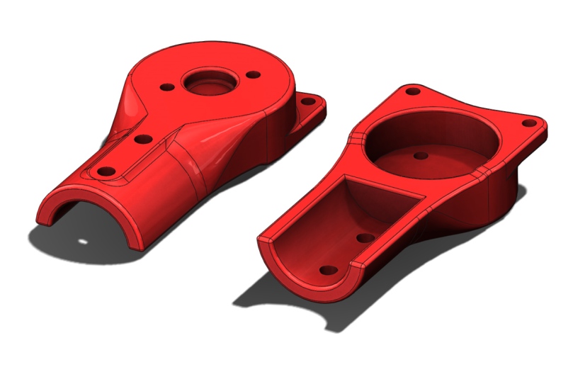
Firstly the outer edge of the the motor mount pieces have been thickened slightly such that these faces are coincident when the two identical halves are clamped on to the tube. Secondly ears have been added at the tip to accommodate fasteners to ensure the two halves are joined solidly.

MC2 009

The intended fasteners have been added to the assembly. If you look carefully at the wires from the motor it can be seen that there is interference with both the bolt head and the nyloc nut. Since I would like to maintain the symmetry here without making multiple variations of the motor mount I will probably change the bolt to a button head and use a plain nut (with thread locker), hopefully this will be of a low enough profile that the wires can ride over them.

Power Distribution & Motor Mounting

A two part updated today. After last working on my concept layout I was without an internet connection (modem failure) to publish my progress.

First up I started fleshing out an idea for power distribution. This idea being a single PCB with all 5 of the ESC’s and a battery connector soldered directly to it. Currently I have not looked at the electrical feasibility of this at all and I expect it could be challenging given the high currents being dealt with. That said other similar sized copters have implemented the same concept successfully. One possible downfall of my approach is trying to do to much in to little space. Complications (read challenges) I have introduced include:

  • ESC’s on both sides of the board, this might make a simple one side +ve the other -ve approach more difficult.
  • Bullet connectors included on board, individual traces will be required rather than simple +ve and -ve planes.
  • 100mm length limit as this is the large size offered by http://dirtypcbs.com/
  • XT60 connector directly soldered to the PCB. This may in fact be a very bad idea a for reliability, a loose battery may tear the connector from the board and fixing that will not be a quick swap without another fully populated power distribution board (5 ESC’s!) ready to go.

MC2 006

In any case getting this concept for power distribution together has meant that I have shuffled the overall layout about again. The power distribution board itself has been dropped low and pushed forward beyond the front boom. The fuselage structure will need to extend forward to protect this. The thrust vectoring servo’s have been repositioned in a vertical orientation in an attempt to keep the fuselage narrow, servo horns were added for a more complete picture.

MC2 005

The next development was to create the first draft of the motor mounts. The concept here is that the motors would first be attached to the mount before the mount is subsequently attached to the arm with its opposite number. I intend to add extra fasteners at the tips of the arms to hold the two halves together. I also need to add some thickness below the motors so that the two halves support each other at the tip whilst leaving a gap at the back end so that the two halves clamp on to the carbon tube.

MC2 008

Whilst the layout hasn’t changed markedly here it does illustrate what the motor mounts look like installed. An entirely different solution will be used for mounting the rear motor.

MC2 007

Power and Control

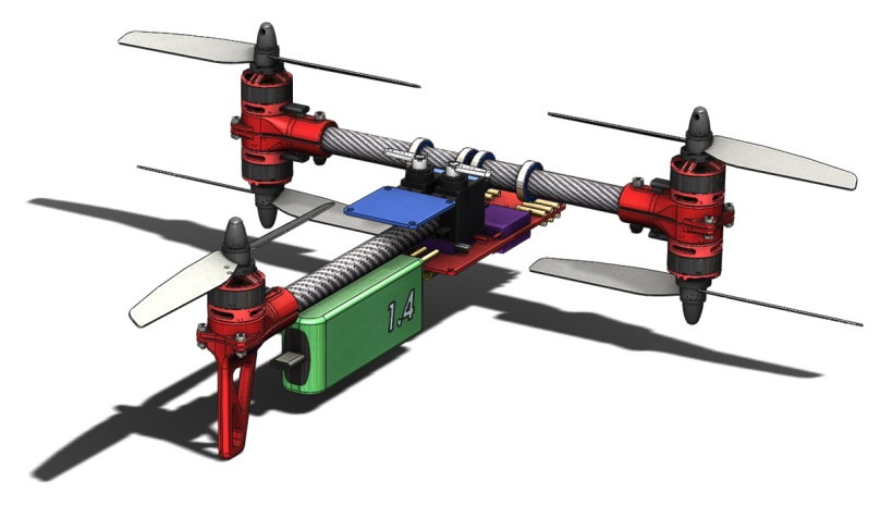
This update is only a small one with the inclusion of the flight control board (blue) and the motor speed controllers (purple). Positioning of the speed controllers is very temporary. I would like to investigate mounting them directly to a power distribution board to reduce wiring. As the layout develops so will my thoughts about what form this board may take.

Given this is looking more and more crowded I also looked at what impact increasing the motor spacing has. Currently, and in all pictures to date, the motor axis are on a 250 mm pitch circle. Increasing this to 280 mm increase space quite dramatically however I feel it is to premature at this point to be increasing the size without determining that this smaller size can’t be made to work.

I have also be wondering on the sense of my idea to use a boom for the rear motor. The popular plate based design holds appeal for ease of assembly and layout however I tend to design within the constraints of fabrication techniques easily available to myself and currently that is 3D printed ‘connectors’ and off the shelf sections.

Components added are:
Flight controller: Naze 32 “Full” Flight Controller (the “Acro” version would also be suitable)
Speed controls: Afro ESC 12Amp

MC2 004

More OEM Bits

This evenings work was modeling a couple more of the OEM parts I intend to build the prototype with. All parts I am working with so far are the same pieces used in the development of Mk.1. Parts added this evening include the thrust vectoring servos and the battery. I had intended to use a bigger battery but putting this one in to the development layout has shown that available space may have other ideas in that regard, an increase of motor spacing may be required as I progress.

Components used are:
Servo: Turnigy™ TGY-9018MG MG Servo 2.5kg / 13g / 0.10
Battery: MultiStar Race Spec 3S 1400mAh 40-80C

MC2 003

MC2 002