Space Cowboy Design SCX-230 LowPro

DSC04772

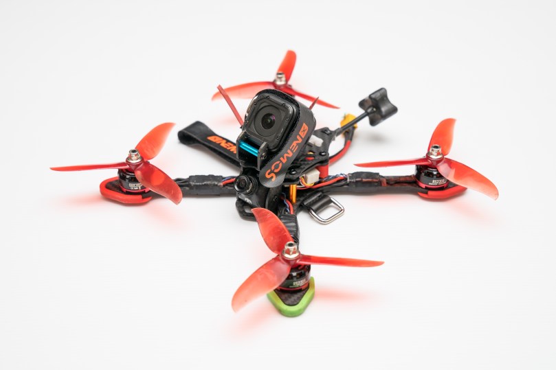
On my recent order of cut carbon from Armattan Productions I included a GoPro mount kit which suits the SCX-230. I’ve been flying this copter for some time now and am very happy with it. It’s a long way from ‘latest and greatest’ gear wise but it is built with quality components and the experience has been better for it. Now being able to watch some of my flights in HD and share them with others has been great fun. To that end this post is primarily to share link some of my recent videos (no edits, directly from a GoPro Session 4).

My primary flying site has a great mix of open spaces and trees:

The rig also came with me on a recent camping trip:

I think I got very lucky with this crash. The only damage was the two front arms, I didn’t even need to straighten a prop:

Fresh PepperF1SH frames

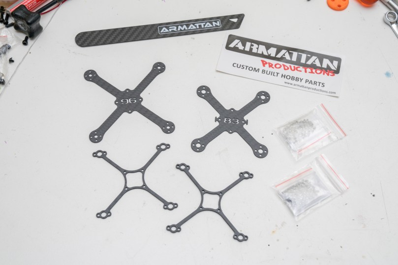
DSC04759I’ve received some freshly cut carbon from Artmattan Productions. That means it’s time for some new PepperF1SH builds, I’ve got plans for at least 3 more. Also seen in the photo above are some titanium screws purchased from AliExpress.

DSC04764
My twig frame as seen mechanically assembled here is unproven, but was inspired by one I saw on RC Groups. I’ve got 1.5mm and 2mm thick versions. They’re stiffer than the 1mm PepperF1SH frame but I don’t know about durability yet.

More to come when they’re flying..

Micro Quad ESC Frame

In an effort to get content flowing here again posts will probably be higher in image content and short notes rather than long form articles.

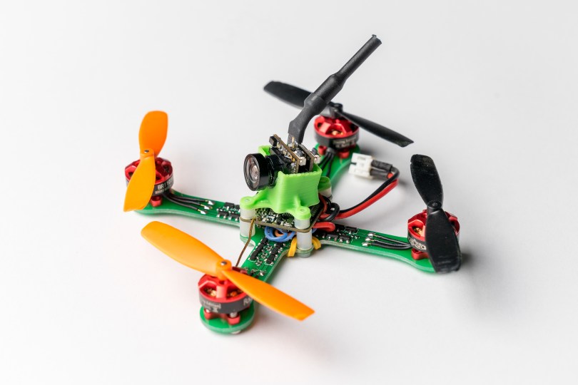
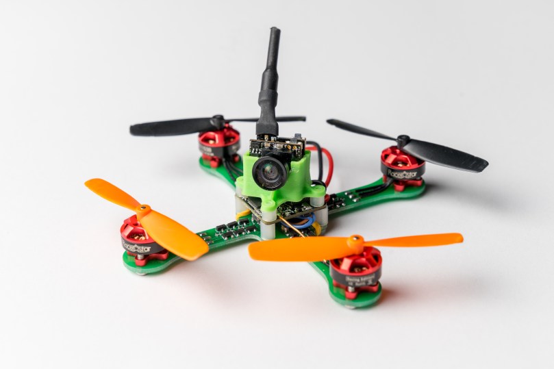
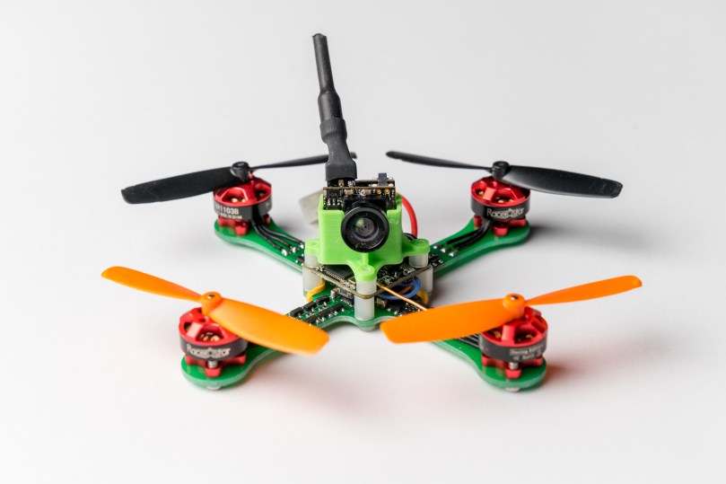
As such this is my latest quadcopter build. A micro 1S quad based on the excellent work of http://fishpepper.de.

DSC04165

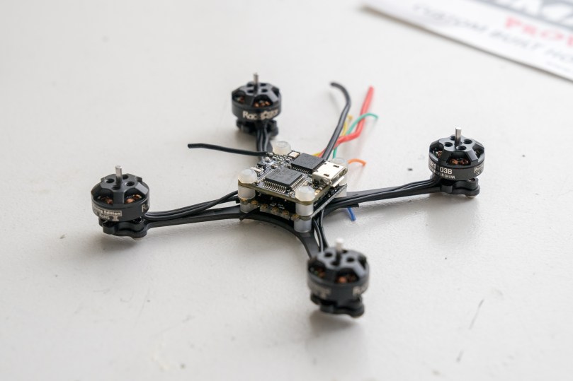
I have used the tinyFISH Flight Controller directly so nothing amazing on my part there (thought the FC itself is an amazing accomplishment). My point of difference, and the reason for this post is the ESC frame. I have created a new board layout which uses the schematic of the tinyPEPPER 4-in-1 ESC but laid out on a PCB that serves double duty as the frame for building the copter on to.

Pair

My initial motivation for this creation was to avoid the wait time of a custom carbon frame being cut. With the time spent on this layout and delays in production I could of just as quickly gone down the more traditional route but this was a fun project and I picked up some new skills. With the tiny size of this copter the frame fits within the common 100×100 size limit of cheap PCB fab houses. I used JLC PCB as a test this time around and for $20 I got 10 PCB’s with 2oz copper. Unfortunately the delivered spec. was not what I was after. The board is 1.6mm rather than 1mm (so much extra weight!) and the solder mask could only be green, the sticking point being the 2oz copper.

In any case it flies as is, there were no problems electrically with the PCB. Assembling the tiny components was challenging my first time around but became easy enough even though I’m only using a soldering iron, hot air rework station and wire solder.

As required by the terms of the CERN open hardware license v1.2 my source files (KiCad) are available under the CERN open hardware license v1.2. Feel free to use the design – but make sure to give proper credit and release all modifications under the same license!

github64
ESC_Frame by aTaylor60

DSC04166

I modelled a new mount for the FPV camera which better suits FDM printing (no support required) and puts the lens on the centre line. There is also a bit more space withing it as I was finding the fishPEPPER designed option just wasn’t fitting the camera I had. A small dab of hot glue in the bottom of the mount ensures the camera stays put. It is available on Thingiverse.

thing_icon_57CM275t mount by ataylor60

DSC04168

To simplify the routing for the PCB fabrication I mount the battery with a rubber band that loops around the standoffs for the flight control stack.

DSC04175

I already have parts and plans for another 2 builds. One will be with this same ESC Frame but using 10000kV motors and another will be using the recommended 8000kV motors on a carbon frame (either my own design or the PepperF1SH design). I’d also like to get another run of boards from a different fab house in 1mm thickness and build a 2S version but that is a little further down the track.

I’ve also got a number of other custom designed but larger scale copters that will eventually find there way onto these pages. So many projects, such little time!

215 Hopper FPV Rebuild

I finally have the design of the 215 Hopper at a point where I think it is fit for purpose as an FPV copter. It can now sustain a heavy grounding without terminal damage. I still won’t claim that it is as durable as a carbon plate design but I am now happy to release it. The camera pod is perhaps the least durable part of the design however I am still flying with the first one I printed and it has served its purpose protecting the flight cam. I do intend to upgrade it at some point but that will probably come after the custom camera pod for my Shendrones Tweaker.

If you’re interested in building a 225 Hopper FPV then you can find all the files you will need over at Thingiverse


215 Hopper FPV
by ataylor60

215H-FPV-22

I have made 2 changes to the previously seen FPV design iteration to realise these durability improvements. Firstly I scrapped the idea of running the motor wires through the arm tubes. Whilst I think this still has merit, for now it was causing more problems than it was solving. I will perhaps look at it again in the future. I have however maintained a similar motor mounting arrangement. All 4 M2 threads are used to attach the motor to the top half of the motor mount with the motor wires aligned with the arms. Separate bolts are used to clamp the motor mount to the arm tubes.

The second change is specifically to do with the clamping bolts on the motor mounts. Now rather than simply clamping on to the tube end and relying on friction to keep it in place I have created a positive interaction between tube and mount.

215H-FPV-18

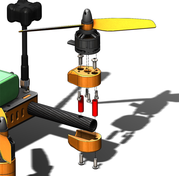
As seen in this exploded view of the motor mount the tubes are now drilled with a 5mm hole to accept the same 15mm M3 standoff that is used throughout the rest of the frame build. The 2 printed parts of the motor mounts then snap over these standoffs and are clamped together with M3x8 button head screws. The only trick to this is that the standoffs must be screwed in to the top half of the mount before the motor is subsequently mounted to that before it is finally installed on the arm.

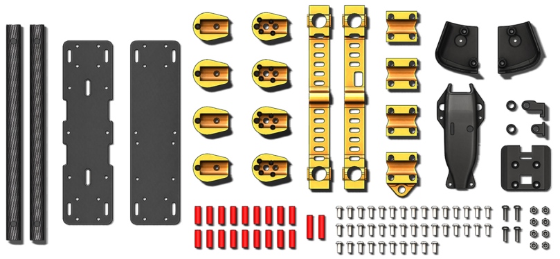
At the same time as making these motor mount changes I decided to keep things simple and remove the LED tail lights. Now the same 2 parts are used at all 4 corners. Speaking of parts, the image below shows all the parts required to build the 215 Hopper FPV edition.

215H-FPV-21

Included are (in order from left to right, top to bottom):

  • 2x 215H 101 12mm x 10mm x 183mm Carbon fiber arms
  • 1x 215H 107 Top plate PDB
  • 2x 215H 106 Bottom plate
  • 4x 215H 138 Motor mount bottom
  • 4x 215H 137 Motor mount top
  • 1x 215H 103 Frame side
  • 1x 215H 111 Frame side with USB access
  • 3x 215H 108 Tube clamp
  • 1x 215H 102 Tube clamp with antenna mount
  • 1x 215H 130R Camera pod right side
  • 1x 215H 130L Camera pod left side
  • 1x 215H 126 Video Tx pod
  • 2x 215H 134 Camera pod spacer
  • 1x 215H 132 Camera pod rear post
  • 1x 215H 133 Camera pod front post
  • 1x 215H 131 Camera pod base plate
  • 18x M3x15 Round standoff
  • 2x M3x20 Round standoff
  • 40x M3x8 Button head socket screws
  • 4x M3x10 Nylon screws
  • 8x M3 Nylon nuts

All the 3D printed parts are printed in ABS with a 30% infill, 3 outlines, 3 solid bottom layers and 4 solid top layers. Colour is unimportant but I find it looks its best if the frame parts are a bright colour (as seen here in orange or previously in red) and the accessory parts are black.

The 215 Hopper FPV is designed around a fairly specific set of components. This is not to say that other parts won’t work on the frame but rather that the positions and space allocation work best with what I have used. My recommended build uses:

  • DYS 1806-2300kV motors
  • 18A ZTW 18A Spider series Opto ESC’s
  • Naze32 Rev 6
  • 25mm Plastic housing FPV camera such as the HS117 or HS1189
  • Lumineer TX5G8 Pro power switch vTx
  • FrSky X4R-SB receiver
  • Pololu 5v converter
  • 5cm 90° bulkhead SMA extension

215H-FPV-20

An important detail to note when assembling the frame is that the flight controller should be in the front half of the craft. The reason for this, as I noted on a previous post, is that the vTx pod must fit around the nylon screws used for mounting the flight controller. There are holes specifically for this purpose in the pod. Another new feature on the vTx pod is the inclusion of the slot seen below. This allows you to see what band and channel is selected on the vTx and also if it is transmitting or not. This small details makes working with this specific transmitter significantly less frustrating.

215H-FPV-19

A lot of the notes I made regarding the initial build (found here) also apply to putting together this FPV version. In lieu of a full write up for this I will direct you to that if your would like to build one for yourself. Also please feel free to contact me or leave a comment here with any questions that you might have.

There are a couple of build notes that do specifically need to be made for this model:

  1. Whilst not strictly necessary I solvent welded the 3 parts of the camera mount together (parts 131, 132 and 133). Durability has exceeded my expectations so that is probably a worthwhile step to take.
  2. As I have left over PCB’s from my first batch I have not modified the bottom board to include a hole for passing the vTx wiring. You will need to drill this just in front of where it will connect to the vTx. It should end up just inside the ‘mouth’ of the pod.
  3. As the motors are now fixed to the tubes drilling the holes through which the mounts pass is critical. They must be aligned end to end. For this I have included part 215H 139 which is a drilling jig. Print two and slide one on to either end of the arm tube. You can then use the flat sides for alignment. I suggest holding the jig with a clamp or vice whilst drilling as the thin wall carbon has a tendency to grab onto the drill bit.

215H-FPV-24

If you decide to build one i would love to see it! let me know about it here or post it up as a build on thingiverse.

215 Hopper FPV Durability

As flight hours on my 215 Hopper FPV platform increase it has become clear that the durability of the design is somewhat limited compared to the more common carbon plate design. The core problem however is not breaking parts, though this has happened, but rather pulling wires out of the motors. When the quad comes down it frequently pulls the motor mount from the end of the tube and as the propellor is often still spinning at a high rate the inertia of that then stopping is enough to pull the now loose motor off its own wires. Part of the philosophy with this design was that the motor could be allowed to rotate on the tube in the event of contact and through most all of my LOS flying this was valid and workable. It has now become evident that the sort of crashes I am experiencing whilst learning FPV flying are too much for this design.

With my first iteration of the FPV version another flaw with the rotating tube fairly quickly became evident. The edge of the hole in the centre of the arm tubes was cutting the insulation of the motor wires. In fact this become bad enough before I realised it was happening that the motor wires began to short through the carbon ultimately resulting in the quad falling from the sky (perhaps about 10m). This was the most significant crash to date resulting in a broken arm and several broken plastic parts as well as the previously mentioned motor pulled from wires problem.

215H-FPV-11

Something odd has also happened to the electronics meaning that 3 out of the 4 motors will not spin up to full power. This problem remains undiagnosed so I have shifted the FPV gear across to my other airframe. In the first image below the spilt insulation is very evident though I don’t think the wires actually shorted at this end, the crack in the tube can also be seen though it was significantly worse when removed from the plastic support.

215H-FPV-12

In this image, at the other end, the split insulation is also evident but if examined more closely there is evidence of burning from the short on both the tube and insulation of the middle wire.

215H-FPV-13

Two decisions have come from this. Firstly I have iterated on the design again with a number of changes which I will detail in a subsequent post. Secondly I am building a more traditional carbon plate design which should hopefully allow for a much better flying to fixing ratio upon which I can develop my skills. Specifically this will be the Shendrones Tweaker and as is my way that won’t be a standard build so there will be a post about that soon too.

215 Hopper FPV Airborne

Over the weekend just past I got my first solid session flying FPV under my belt. This of course means, as the title of this post also states, that my FPV build of my 215 Hopper design is complete.

215H-FPV-7

The build wasn’t quite as smooth as I had hoped for a few of reasons:

  1. The new routing for the motor wires, through the arms, came up short. An extra 10mm or so and I would have run them as they were. As it is though I ended up extending the wires. This also made soldering them to the ESC’s a simpler task so it was a good move in the end. Despite the extra complexity in the build I am very pleased with how this aspect of the design turned out.
  2. My initial design for the base plate of the camera mount fouled on the zip ties that hold the ESC’s in place. I had to shorten that and print the new design.
  3. My initial design for the video transmitter carrier fouled on the heads of the screws  that mount the flight controller. This was actually 2 errors rolled into one. I absentmindedly assembled the frame back to front with respect to the flight controller. i.e. the flight controller is in the front half rather than the rear half. This doesnt make any difference flight wise but it would have meant the carrier wouldn’t have fitted up even if I had accounted for the flight controller screws.

The second failure with the video transmitter carrier design is also the same failure as with the camera mount. It is a lesson that I have learnt the hard way on to many occasions and it is thus; If you are using CAD use it fully, every detail should be represented in your model. If you leave something out, either intentionally or inadvertently it will come back to bite you at a later stage of the project. In the case of the camera mount I didn’t even have the holes for the zip ties let alone the zip ties themselves. For the transmitter carrier I didn’t have the screws in my model. Thankfully having the 3D printer on hand meant that I could correct these errors in the space of an evening and was ready to fly on saturday morning.

215H-FPV-8

With the new build came new batteries, I am now flying on 4S 1400mAh batteries (hobbyking) and loving it. I went with the higher discharge rate option, it is perhaps overkill but it means I get much further through the capacity of the battery before voltage sag starts hitting my warning levels.

215H-FPV-10

Other than the mentioned hiccups the build was much the same as the ‘base model’ 215 Hopper as I detailed here. I will put together a similar writeup for the FPV model in the near future. The design files will also be available. On top of that I now have a big stack of PCB’s for the build which I will make available for purchase. A full frame kit with hardware and 3D printed parts may also be an option.

215 Hopper FPV Build

After the mad rush of getting my ultimaker operational and making my Iron Man mask I have finally been able to get back to my FPV build of the 215 Hopper. I now have all the frame components made and there are some significant changes from the original.

215H-FPV-1

To start off with though, a tale of my first FPV session. As soon as I had all the pieces needed to fly FPV I had to try it. Knowing that my dedicated FPV build was still a couple of weeks away I rigged up the Hopper, mostly with cable ties and temporary wiring but also my first iteration of the camera mount/crash protection. The first couple of batteries were trouble free. Landings were rough but I was mostly taking things very easy, it was certainly a cool experience and all the gear performed flawlessly.

On the third battery I hit the ground quite heavily. Looking back at why I have realised that I basically flew it into the ground forgetting that maximum lift (i.e. quadcopter level) is going to be achieved with the camera pointing mostly towards to sky. When I came down I was looking mostly at the ground despite thinking I was pulling up. As can be seen below the airframe itself suffered no real damage. The motors all twisted on their tubes but that is easy to correct. Unfortunately one of the motors also came off its tube, the spinning prop cut one of its wires and pulled it out of the motor at the same time. The VTx also collected a lot of dirt given that it is exposed beneath the airframe. The roll hoop around the camera snapped as the quad tumbled, I guess this means it did its job of preventing the camera being a point of impact. All these factors combined meant that I decided not to fly with this cobbled together rig, I would wait until everything was in its proper place.215H-24

To address the wire cutting issue I have decided to route the wires through the tubes rather than hanging them loose around the arms. To achieve this I have had to redesign the motor mount. Previously the 2 parts of the motor mount and the motor were all clamped to the tube using the motor mounting bolts however the spacing meant that they could only just fit around the 12mm tube. This forces the wires to exit at 45° to the tube, in reality this would probably be fine but my sense of details told me to rotate them so the wires exit parallel with the tubes. To do this the new motor mounts incorporate their own M3 clamping bolts with captive nuts. To assemble them the top half of the tube clamp is bolted to the bottom of the motor (now using all 4 M2’s) before the two halves are clamped around the tube. The new mounts also include a slot on the end for passing the wires in to the tube.

215H-FPV-3

As mentioned in one of my design posts the rear motor mounts now also incorporate a small pocket for LED tail lights. I haven’t designed the tiny PCB for that yet but the image below shows where they will be with the power supply wires hanging out. I’ve been really impressed with the detail I have been able to model in to these parts. The wire grooves through the middle of these are only 1.5mm wide but are reproduced in perfectly useable fashion without needing to make any adjustments to my default print settings.

215H-FPV-6

At the rear the modified tube clamp for mounting the antenna has come up nicely but I may need to make a counter bore for the nut. The antenna itself is only just getting tight. All of the tube clamps are also modified on the inside with a hole for the motor wires to come through.

215H-FPV-4

Underneath I am very please with the VTx housing. I completed the details of its design after receiving my Lumenier TX5GPro Mini 600mW (GetFPV). It now sits inside the housing with no extra support required and is protected by thick ribs on the inside of the housing. The wires will be routed through the PCB rather than coming out the front as in the photo below.

215H-FPV-5

And finally the camera mount. There are a few pieces to the current solution but it allows for a lot of flexibility and feels much more robust than my first attempt. The camera is held in place by the clamping effect of the bolts in each side, it can be adjusted from 0° to 45° above horizontal.  To install it the base plate is attached to the airframe clamping the two posts in place before the threaded standoffs are inserted and each side of the housing is clamped around the camera.215H-FPV-7

I also decided that the less conspicuous look of black was better than a big red blob on the front.

215H-FPV-2

Next up is all the internals. I already have everything on hand so it won’t be too long before this is in the air.

Ultimaker Operational

It has been a bit longer than I would have liked since my last update. A lot has been going on, most of it to do with 3D printing. As the headlines states my Ultimaker tribute is now operational, so far I am very happy with its performance. There is however still room for improvement, particularly on the reliability front, and I certainly wouldn’t call it finished yet. At my last update on progress for this build I was still waiting for the electronics to arrive.

Once I finally had all the parts on deck I dived in to wiring everything up so that it was basically functional. Beyond a general excitement to see it functioning I now had a deadline hanging over my head, in just over 1 week a friend was celebrating a birthday with an ‘at the movies’ theme and I had come up with a costume idea that resonated with me that would required a lot of 3d printing to pull off. I still had the Steelcity Electronics printer on my bench but I was running it flat out printing bits for his costume. I also wanted to use PLA for its improved stability and the DaVinci is not yet set up to cope with that. So I had put myself in this crazy position of needing my new and untested printer to function really well straight out of the gate.
Thankfully it generally didn’t disappoint! More on that project at the end of the post for now though the printer build itself.

UM2T-9

My first order of business was to get all the electronics in roughly the right place so that I could measure wire lengths and terminate them with the appropriate connectors. Unfortunately this is also where I hit my first stumbling block. The contacts I purchased for the JST connectors used for the limit switches and motor connections to the control board where the wrong series. I had the correct housing but the wrong crimp. Thankfully the spacing on the pins is 0.1″ so for now I have rigged it up using terminal strip connectors. The only significant change I have made to the wiring layout compared to an official ultimaker is to run the hot bed connections off the other side of the build plate. It is not yet installed but I will be running a cable chain on this side tucked in to the back corner rather than in the more traditional left side position.

With the wiring mostly sorted (if only in a temporary sort of way) I had to tidy up the last critical mechanical details which were:

  1. Drilling out the build plate to accept the larger diameter POM nut supplied with the Z-axis screw I am using. I also tapped holes for it’s fasteners however only 2 of the 3 would fit without overlapping any of the existing holes. I have however installed the nut in its self supporting orientation so I am not concerned about this.
    UM2T-11
  2. Drilling holes so that the fasteners on the 90° brackets could be tightened. As mentioned in the previous post I have forgone the Plastic corner joiners in favour of full metal joints. This is achieved by a combination of the angled brackets shown here and the previously discussed end tapping of the perpendicular members.
    UM2T-10
  3. A full frame and gantry build up with threadlocker throughout. This was more time consuming than anticipated, applying threadlocker seemed to slow things down markedly however everything went together without much drama. After a couple of hours of assembly I couldn’t get the frame to sit perfectly square and true but it was very close so I forged ahead and locked down all the gantry pulleys and sliders.

With everything mechanical in place I want back to the wiring and connected everything in it’s temporary but functional state and fired it up for the first time. No magic smoke so I was of to a good start. It was here that I faced my first significant frustration and it was all to do with my long Z-axis. I had assumed that simply changing the upper Z-axis soft limit in Marlin and uploading the recompiled firmware would be all it took however something there is slightly amis and I’m not entirely sure what just yet. To get it running I had to disable the lower Z-axis soft limit (i.e. the end with the limit switch) so that the bed would come all the way home without reporting a Z-axis limit switch error. Even still though the firmware doesn’t seem to properly understand its build envelope at all times. It will start in the right spot though so that is all I need for now.

The last piece of the puzzle was a way to hold a spool of filament. I have seen plenty of fancy bearing mounted spools on thingiverse but in the end decided that to get things started I would knock up a quick solution using a piece of leftover 2020 extrusion. I came up with a very simple beam clamp to hold a short section of extrusion on top of the rear mid member (which doesn’t exist on the standard size version) and a small bracket to stop spools sliding off. Both pieces can be found on my updated remix of Jason’s design on thingiverse.

UM2T-12

UM2T-13

With that in place it was time for some heat. I manually set some temperatures for both the build plate and the hot end so that I could verify they were both working, all was as expected. I tightened the hot end whilst it was hot and then ran the auto tune sequences for both the bed and the hot end, the hot end being most important since I am using the E3D v6 rather than the standard Ultimaker unit. Once an updated copy of the firmware was in place, containing the new PID values, I checked the extruder was performing as expected and decided to jump right to a test print.

The first signs were not good. Bed adhesion was poor and there were big gaps between lines. By this stage it was in to the early hours of the morning so I decided to leave it and come back to it with a fresh perspective the next day. This proved a wise decision as it took me only minutes when I was next in front of it to realise I never changed the default filament size from 3mm to the 1.75mm that I am using. Changing that obviously made a world of difference and the new test print was going down very nicely. After 30 odd minutes of solid printing I cut the test piece off and decided to jump head first into my urgent project, fine tuning be damned, I didn’t need precision and the quality was looking better than good.

Turning into Iron man

If ever there was a movie character that I could see myself as it is Iron Man/Tony Stark. Genius billionaire playboy philanthropist, that’s my sort of jam.
Unfortunately I don’t have a great deal of photos of this process as I did it all into just a few days. I started printing parts for my Iron Man helmet, as supplied by MIPRESIDENTE on thingiverse (my make of it is here), on the tuesday night, the party was the following Saturday. Ultimately I was a long way off a complete helmet but I made enough parts for a complete mask which was all the identity I needed. I glued the parts I did have finished to a cap with the brim cut off so that it could easily be worn.

IM-1

Also from thingiverse was the Wearable Arc Reactor by MishaT. It was not 100% complete either so I chose to wear it hidden under my T-shirt with only the lighting effects shining through.

The finish quality is a long way from perfect but from a distance looks very convincing. To get from the raw print to the finished product, involved:

  1. Breaking away support structure.
  2. Sanding raw plastics to remove significant layer lines.
  3. Coating with XTC3D. (I will have to experiment with this more as I don’t feel like I saw the full benefit from it)
  4. Sanding.
  5. Spraying with plastic primer
  6. Sanding.
  7. Spraying with black base coat in the hope of a deeper colour.
  8. Spraying with gold and/or red (the jaw piece has both colours on it if not separated before finishing).

As an indication of what I was working with shown below are the two side panels (which I didn’t end up using) still on the bed but almost complete. I think I added a lot of time to the print with excess support material but when I started the print it was a case of ‘just make sure it works’.

UM2T-15

There was one very significant problem I faced whilst printing these parts and that was a feeder which kept grinding the filament causing extrusion to stop. At one point this happened when I was more than 12hrs deep on the 3rd attempt on the face plate and jaw piece print. This was a make or break moment. If I had to start it again I probably wouldn’t have been able to make the mask work. Thankfully with a little bit of trickery I was able to save the print by restarting it at the layer at which it had failed. This post is long enough as it is without details on that so look out for a how to on restarting a failed print with some manual G-code magic in the future.

I do intend to complete the helmet print. If not to be worn then at least as a show piece. I will also strip it and refinish it to a higher standard, hopefully with a more accurate red on it too. With the pressure of the party deadline behind me now though I will finish the printer itself first (whilst printing the 215 Hopper FPV parts, I just can’t help myself). The three big items to tick off the to do list are:

  1. Terminate all of the wiring correctly and generally tidy that up.
  2. Install the cable chain for the hot bed wiring.
  3. Have the enclosure panels made (for improved thermal stability whilst printing ABS).

There are also several other odds and ends like lighting which need to happen but they will come further down the track. I will at some point also replace the vertical frame members and Z-axis rods as it turns out there is still more than 80mm of thread left on my Z-axis when it reaches the print head.

For now I will leave you with this teaser on what I am planing for the enclosure.

UM2T-14