215 Hopper – Build 2

215H2-2

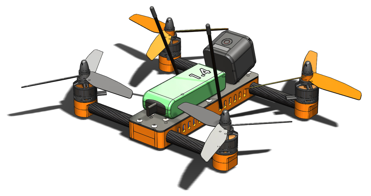
I have been a bit slow in getting this report together but I am pleased to say the as of late last sunday evening my second build of the 215 hopper design is airborne. For anyone keeping track that is just a 6 day turnaround from lost to flying again. There are a couple of things that worked in my favour to achieve this.

  1. Firstly the 3D printer from the workshop of SteelCity Electronics is currently on holiday to my workbench, as such I was able to start printing replacement parts immediately (more on this topic in the near future, I’ve got a big build cooking).
  2. The guys over at NextFPV actually had stock of every replacement part I needed. I expected I would need to order various bits from multiple sources internationally but discovering everything was stocked locally was a pleasant surprise. On top of that the service they offer is exceptionally fast. I am a very happy repeat customer of theirs. I the future I will gladly purchase through them whenever possible (hopefully there is an FPV setup in my future).
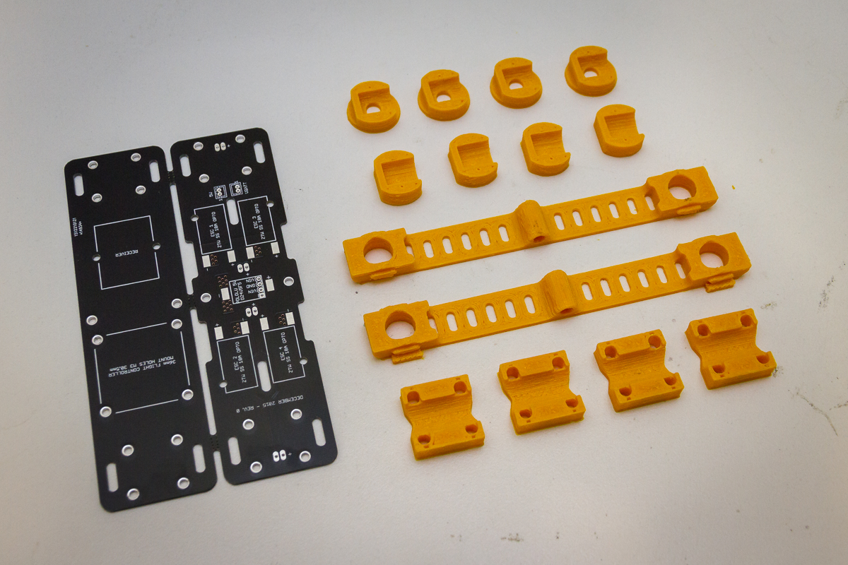
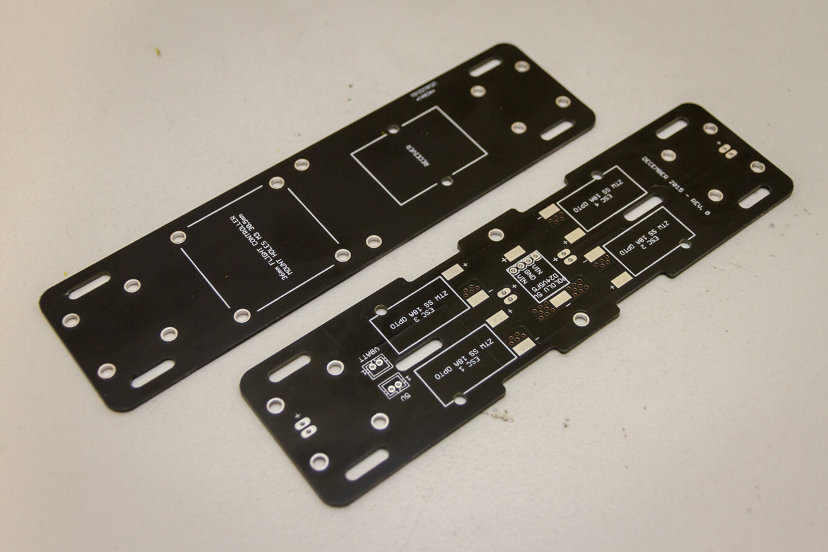
  3. When ordering parts for the first build I doubled (or more) quantities of the various bits of hardware so all of that was on hand. The PCBs were taken care of as DirtyPCB’s supply 10 per order by default.

With the rebuild I got the chance to address a few of the shortfalls of the first build. Changes included:

  • Shortening ESC signal/ground wires so that there was less wire bulk in the body. it was a bit challenging squeezing everything in to the first build.
  • Direct connection of motors to ESC’s. On the first build I needed to join the motor wires with the ESC wires as the motor wires were cut to short from the Spidex 220 build. In reality this is still not a very practical solution as the wires first need to be passed through the side plates. However for the sake of minimalism I stuck with it.
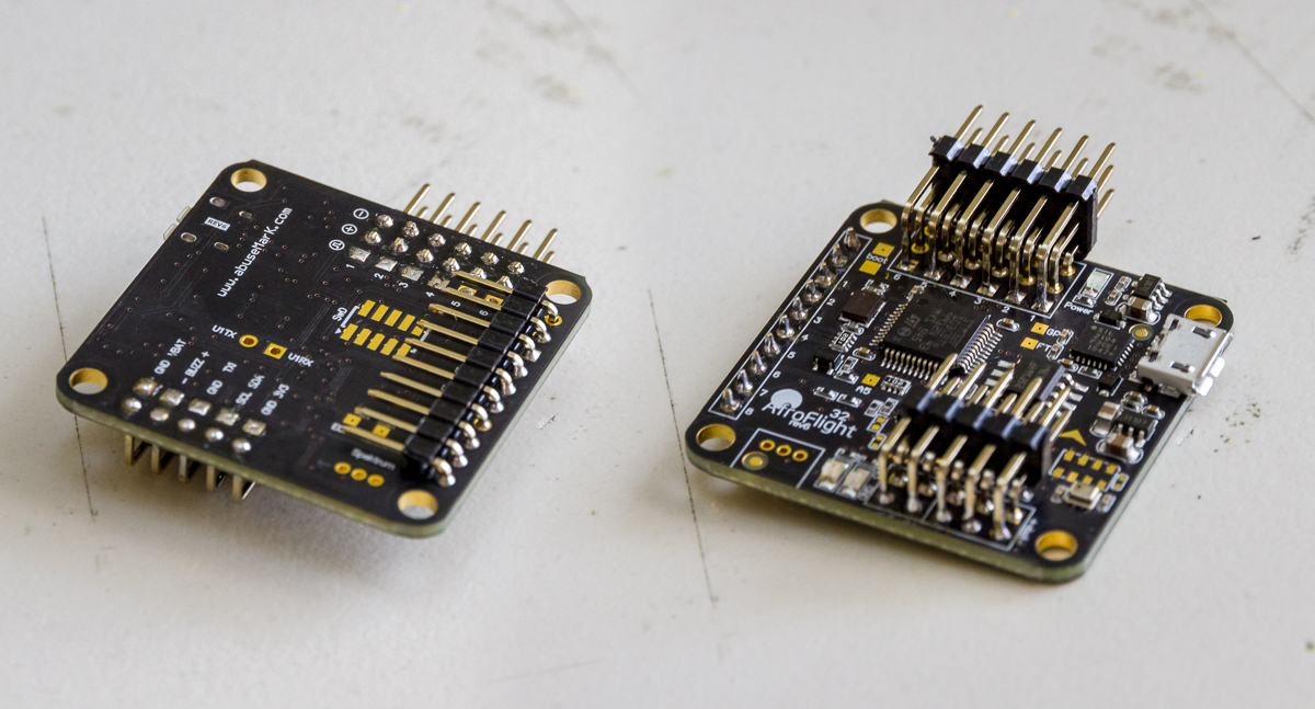
  • Externally accessible USB. This is the most valuable change from the first build and is thanks mostly to the change in location of the port on the Naze32 Rev. 6 board. I also printed a unique side plate with an opening to suit.215H2-3
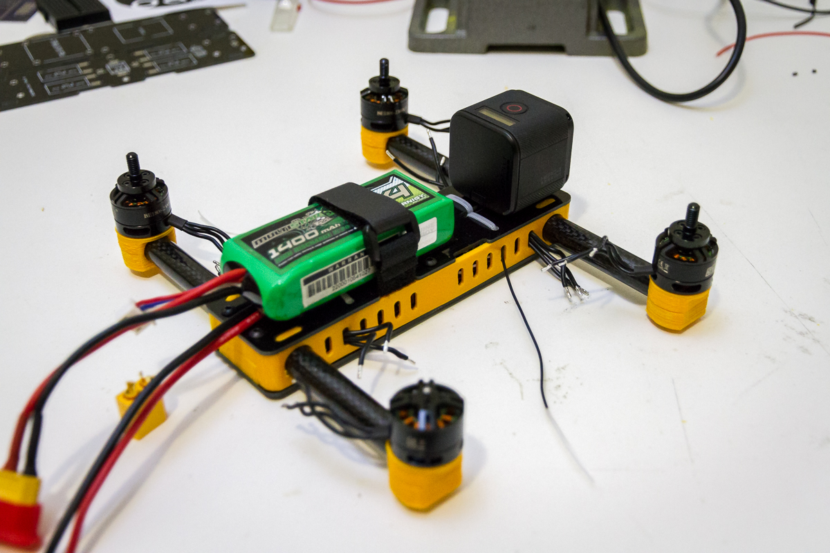
  • The upgrade to the Nae32 Rev. 6 also allowed for very tidy connections all around (no more soldering wires directly to the board). Seen in the photo below is the way I have installed the pin headers on the Naze32. 90° headers are used on all connections. The ESC outputs are installed in a fairly typical configuration. The RC input connections are under and towards the centre of the board and the extra features (Vbatt, buzz etc.) are directed back across the board.215H2-4
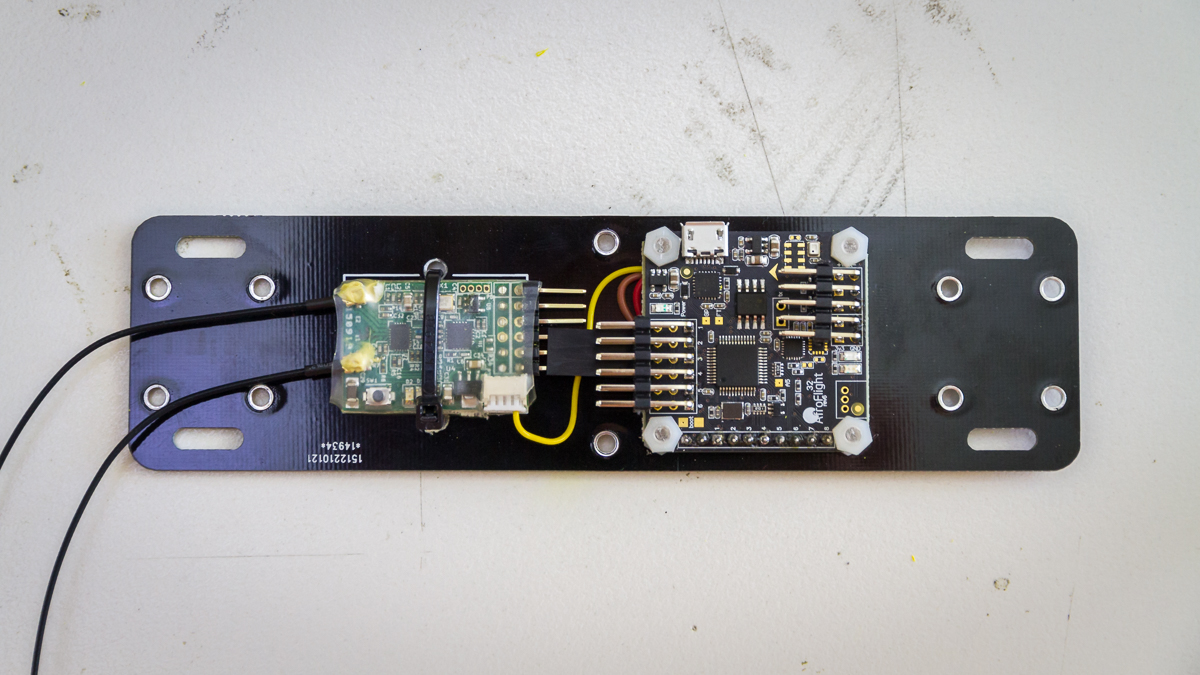
  • SmartPort telemetry. Rather than trying to fit a buzzer inside (which becomes surprisingly large in such a small space) I connected the SmartPort on the X4R-SB to a soft serial port on the Naze32. A buzzer will fit inside but for now I am relying on the telemetry to know the status of my battery. The photo below shows how tidy this setup is. Also note that for clearance to the ESC connections on the Naze32 I have to trim the top row of headers from the X4R-SB.215H2-1

The only quirk with this build, and I find it strange given that it is newer hardware, is that LuxFloat can’t run reliably ( I had no problems with it on Rev. 5 hardware). It may in fact be the extra processing load from the soft serial so I will have to check into that further.

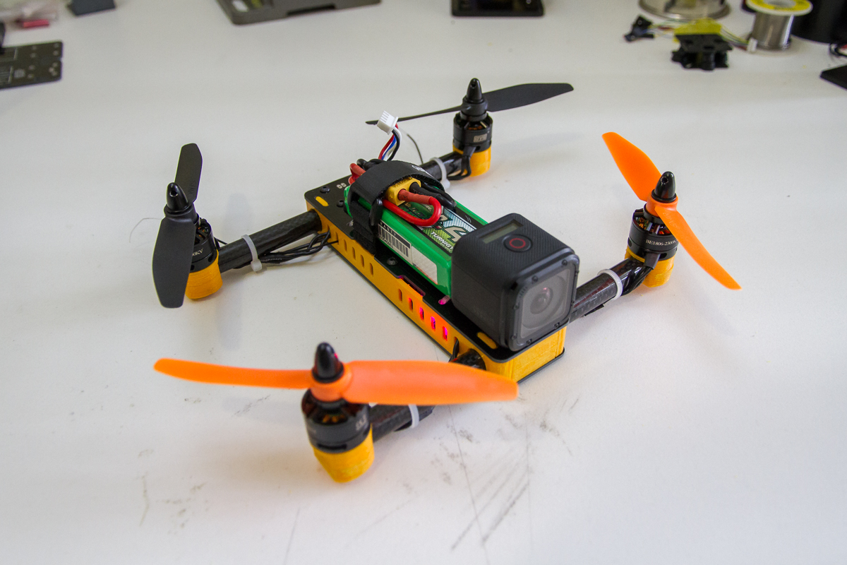
Next on my agenda for this copter is to get the GoPro mount(s) sorted. Then put together a more thorough look at the design and build process with a full bill of materials and files if you would like to build you own.

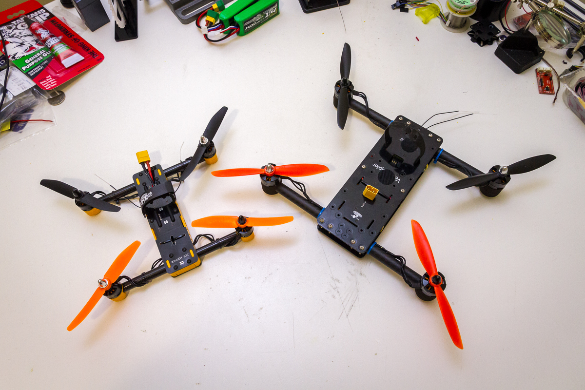
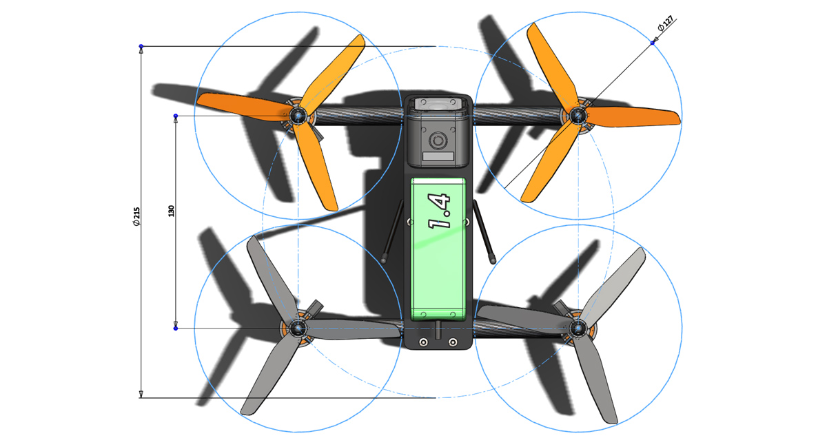
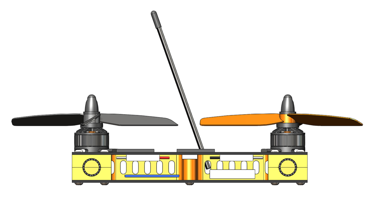
Given that the design of the 215 Hopper was inspired by the FliteTest VersaCopter I thought a family photo was a fitting way to end this post.

215H2-5

Bitter Sweet 215

This shall be a brief post of 2 parts, the first sweet, the second bitter.

To start with I have completed the build and first flights. The photo below is just after completion and ready to take to the air. I very happy with how it has come together. Admittedly there are a couple of problems and mistakes to address but for a first iteration I am very happy with it.

215H-12

Here the 215 Hopper can be seen airbourne on its first battery. Admittedly, the very first hover attempt was a complete failure as I had the motor connections mixed up side to side. After correcting that issue a successful hover test was completed indoors. I was immediately struck by how much more stable it was that its predecessor, the Spidex 220, and that right there was the main reason for starting this project. Success!

215H-11

I have not yet mounted it but in the future I will fly a GoPro session with this platform looking something like this:

215H-13

Now for the bitter part. On just the 5th battery I lost the 215 Hopper. I am not going to try and make excuses, I got a little too far away, that’s not very far for something this small and fast, orientation became difficult. Before I knew it and before I could regain my composure the 215 Hopper was but a small speck high in the sky and a long way away. The signal began failing so I reduced the throttle to try and bring it down gently, more out of concern for where it might land than to protect the copter itself. Evently the signal was lost. I did a few laps of the neighbourhood but my chances of finding it were slim. Most disappointing was that it likely came down over a residential area. I always like to think that I am responsible with where and how I fly and am aware of my surroundings but today I let the community down. I can only hope that it hasn’t caused any damage or injury.

If you have found the 215 Hopper (this is the only one in the world) in the Fairy Meadow/Wollongong area then please drop me a line via the contact page.

215 Hopper Sneak Peak

It has been a while since my last update. Primarily due to the holiday season followed closely by an international getaway which spanned several weeks (some photos from my adventure will appear here in the near future). Since my return I have started to put together the 215 Hopper. It is not quite complete yet, there are still some wiring details to complete/tidy up however it is close as can be seen below. After the maiden flight I will put together a full write up on the parts, build, what I’ve learnt and how it has worked out.

215H-10

This progress also means that the Spidex 220 has officially been decommissioned.

215 Hopper Ready For Build

Thanks to my friend over at Steelcity Electronics I now have all the required 3D printed pieces on hand to build my 215 Hopper Quadcopter. Unfortunately I was a bit distant from the printing process as our schedules simply didn’t overlap at this time of year. I had hoped to have a closer look at it and learn a bit more throughout the process. That will Have to wait for next time. There is some cleanup and finishing work required as part of the build process but that was by design to ensure a nice fit.

215H-1

Also shown in the photo above is the printed circuit board as received from DirtyPCBs. They are my go to for prototype PCB’s at the moment as their prices and options really can’t be beaten so check out what they have to offer. I will also let you know that the 10cm x 10cm size they state as the limit for the higher price point is not in fact a fixed limit. This board (fabricated as a connected pair as shown) had overall dimensions of approximately 15.5cm x 8.5cm which is just over 130cm². Thats an extra 30% more area that the quoted size of 10cm x 10cm and they were made without a question or hold up.

215H-2

This was the first time I produced connected boards. DirtyPCBs is particularly suited to this as they will happily cut internal profiles/slots at no extra cost. The snap tabs drilled with small holes approach worked very well and the edges clean up easily and quickly with a small file. I have found a couple of small errors on the board but no show stoppers thankfully.

Next up will be a full bill of materials and build log. If everything works out then I will also supply the files for 3D printing should anyone wish to duplicate what I have created. That however (and unfortunately) will have to wait several weeks.

215 Hopper – Print Ready

Visually not a lot has changed since my last update. In preparation for printing most changes have been minor dimensional tweaks. Generally speaking the clamping interfaces are opened up slightly to ensure they go together easily and actually clamp to the tube. Fastener holes are closed up slightly to allow drilling of a clean hole after printing.

215H-09

One of the last unanswered questions I had with this design was where the battery connector would join to the power distribution board and how it would generally fit into the layout. My initial plan was to run it out through a grove in the outer surface of one of the end clamps. The reality of this is that there is very little space between tube and the plates on each side, certainly not enough for 16AWG silicone wire (as fitted to the battery) without squashing it. The plan instead is to run the connecting wires out through one of the slots which can now be seen in the top plate above. The battery is raised with the self adhesive rubber ‘feet’ stuck on top. Also now visible in the image above are the cutouts to accommodate a battery strap or two.

215H-10

I’ve also done a lot of the work getting the top board laid out. My approach with this is more ‘suck it and see’ than design perse. I’ve not checked current carrying capacity of via’s or the +ve and -ve planes. The board is laid out with:

  • Direct connections for battery power to the escs
  • A place for the 5v step-down
  • 5v accessory connection points front, rear and centre
  • JST connector for 5v connection to the flight controller
  • JST connector for battery voltage to the flight controller.

I’ve been debating how integrated to make the bottom board (hosting flight controller and receiver). I think it will probably be a better choice to keep it simple and mount these components with fasteners or double sided tape rather than trying to solder them in permanently. I am however a bit of a sucker for the clean look of soldering them in directly as impractical as this is for servicing. Stay tuned for an update on this front, I will need to make a decision in short order as I will now be waiting on fabrication of these for assembly.

215 Hopper Parts

With another 40 minutes on the clock I have added the final detail to the chassis structure for the 215 Hopper. All that remains now for these parts to be ready for printing is some minor tweaks to be sure everything will fit together.

215H-06

In order to positively hold the ends of the side pieces I have added a small tab to the top and bottom. These tabs will snap in to slots cut into the top and bottom plates. My plan initially was for the side pieces to key into the centre clamp pieces but in order to achieve this in a robust manner I was concerned I would have to give up to much of the clamping material. Also of note are the tapered faces I have added to the join surface. This change in shape of the seam should help secure the side plates in a longitudinal direction.

215H-07

When assembled the design makes for quite a tidy little package if I do say so myself.

215H-08

Laid out flat, this is what a full ‘kit’ of the core printed parts will look like. There will still be other non-critical items such as the antenna tube mounts to add to this print list.
To complete the build of the chassis the following pieces will also be needed:

  • Top & Bottom Plates
  • 12mm tube (any will work but I’ve got some carbon tube on hand which was purchased for the MultiChase Project)
  • Fasteners

Speed Modeling – 215 Hopper

At the end of last week I found myself at the intersection of 3 lines of thought:

  1. What could I transfer the flight systems on my Spidex220 to for a more rigid platform.
  2. A friend has a FDM style 3D printer. I have reservations about the tolerances achievable with it for printing the finer parts of the MultiChase Project (which has always been designed with SLS printing in mind). What can I do to involve him and his printer.
  3. How quickly I can come up with a viable solution to 1 and 2.

These thoughts have resulted in a speed challenge of sorts for myself. I have decided to come up with a simple quad that I hope will be printable on a basic FDM printer. I’ve not got any hands on experience with the equipment but I figure if I keep the design simple and the tolerances forgiving then I can’t go too far wrong. I don’t want to divert too much time away from the MultiChase Project hence the speed challenge.

After 3 hours work spread over 3 sessions I have come up with the framework for the solution. The motor spacing is slightly smaller than the Spidex220 I will be cannibalizing. Motor spacing is 215mm as hinted at by the name I have given it, 215 Hopper.

215H-02

The design is heavily inspired by the Flite Test VersaCopter. The layout is basically identical only it is much more compact and uses 3D printed parts rather than laser cut plates. Hopefully with more material supporting the tubes durability will be better.

215H-05

All of the flight electronics, including the ESC’s are carried inside the chassis. ESC’s will be attached to the top panel (and power distribution board), whilst the flight controller, 5v regulator and receiver will be on the bottom panel.

215H-04

The ESC’s I have been using in the Spidex220 have not inspired a lot of confidence, often exhibiting inconsistent performance. As such it took very little for me to decide to try something else. When they didn’t quite fit the width I was targeting they were dropped in favour of a different design, the ZTW Spider Series 18A Opto Lite‘s. The lack of a BEC on this ESC has necessitated the inclusion of a 5v regulator to power the flight controller and receiver.

215H-03

In isolation the 215 Hopper will look like this.

215H-01

With the battery, a 1400mAh Multistar LiPo (3S shown but I might get some 4S packs if everything works out), and a GoPro Session on board a real sense of scale hits me in the face. Its very compact! As hinted at by the presence of the GoPro I hope to add FPV hardware in the future however I am not designing with that as a requirement.

There is still some detail to work out on the side plates and I need to design some clip in antenna tube mounts. Once that is sorted I will make another post showing the assembly detail and it will then be ready for printing. On the time front, the quoted 3 hours is exclusively CAD time. I have spent probably that much again looking for and purchasing various bits of hardware to make this happen but I am quite pleased with progress.