Boom Control Belts

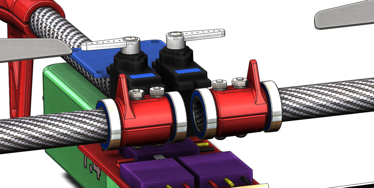
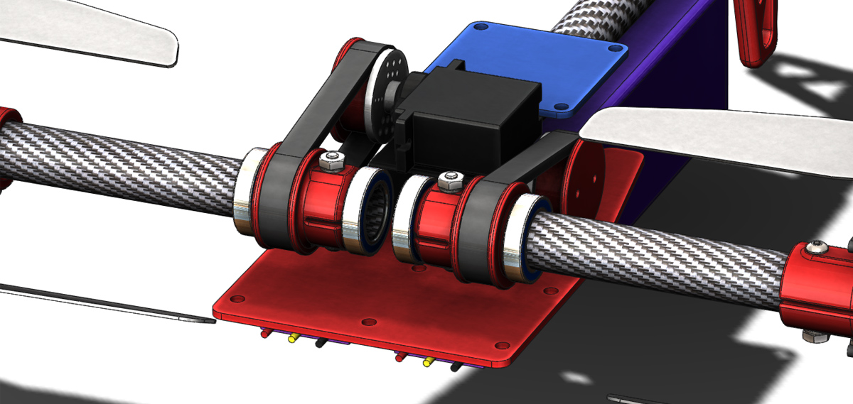
After looking at the range of motion that was going to be achievable with the previously shown boom control arms I was dissatisfied. Only about 70° was realistic. As a rough goal I would like to achieve 135° (90° forward and 45° backward). To get this range of motion and maintain a compact envelope I have decided to investigate the use of a belt drive system. Shown below is the layout I have come up with. The servos are laid on their side and stacked on top of each other and custom pulleys are used at both ends. It may be possible to source a pulley to fit the servo directly but at this stage I have not come across a source so I intend to pursue a 3D printed pulley attached to a standard round horn.

MC2 019

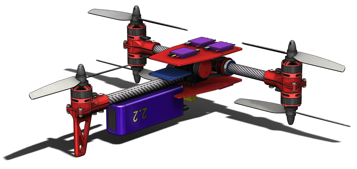
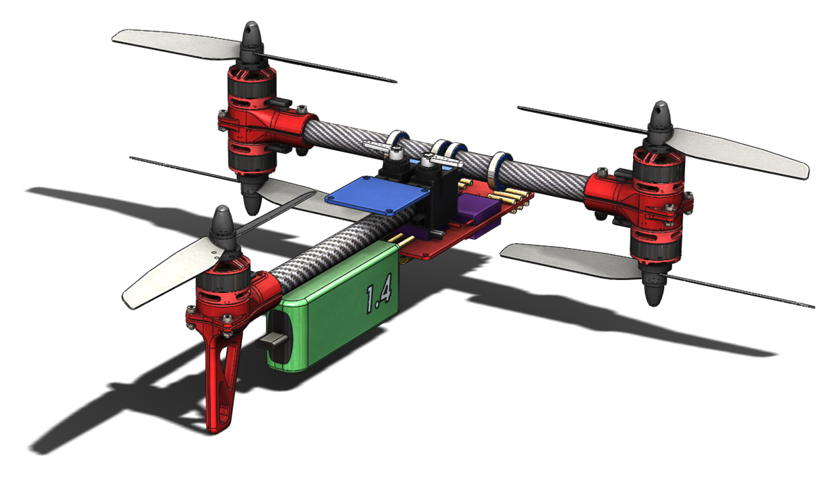
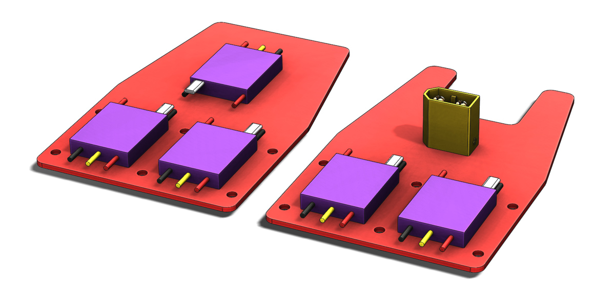
The power distribution philosophy has also seen some development. Primarily I have split the ESCs onto separate top and bottom boards. These boards will also serve as sandwich plates on the outsides of the internal structure (supporting bearings, servos etc.). I’ve also decided to forgo the use of board mounted bullet connectors and instead solder the motor wires either directly to the ESCs or onto the power distribution boards. I learnt from the construction of the Spidex 220 that this is really not as much of a complication as I had imagined it might be. The extra board real estate also opens up a good spot for the XT60 connector, the battery wire would loop around and in on itself to connect.

MC2 018

All together this creates a fairly tall stack height. As I develop the conceot further I hope to find ways to minimise it.

MC2 017

Boom Control Arms

I’ve been spending plenty of time fiddling with and flying the VersaCopter since getting it airborne so progress on this project has slowed somewhat. I did put a little bit of time into it today. Firstly I decided to bump the motor spacing out to 275mm, up from 250mm, that is to say that the centre of all the motors fall within a 275mm circle. Hopefully this will allow me to get the larger battery to work. As can be seen below it is substantially larger.

MC2 014

MC2 013

I also created a first draft of the boom control arms. This part serves a dual purpose, it is the bearing spacer and the arm for controlling the rotation of the booms. My intention is to make the bearing carrier an interference fit along the axis of the boom to keep everything tight through preload. This necessitates the bearing spacer and merging that part into the control arm is a weight efficient approach. My primary concern currently is that the arm itself looks rather small and possibly not strong enough. I have also not looked at the movement of the arm to check for collisions. These will both be assessed down the track.

MC2 015

MC2 016

The Joy of CAD

Sometimes when working with SolidWorks I find myself spending a lot of time making sure that the model is spot on down to the last edge or vertex rather than considering the role of the part in the project at large. Today was one such time, I have been working on the rear motor mount. I will make my point about CAD shortly but first some background on the rear motor mounting.

One of the hangups that I have had getting a start on this part of the design was trying to decide exactly what level I would like to have the motor mounted at and hence at what level the propellor would be spinning. The reason for this indecision is tied to the the Mk. 1 prototype. When flying forward the Mk. 1 would pitch nose up. My suspicion is that the center of drag in a vertical sense is mostly influenced by the spinning propellers rather than the frame. Given that the centre of forward thrust is level with the frame and not the propellers a pitch moment is created causing the rotation. The logical progression from this assumption would be to get the centre of thrust in line with the level of the propellers and test again. For this Mk. 2 design that would mean getting the rear propeller level with the front boom. That however introduces its own set of problems mostly to do with finding space for all the components, particularly the battery. For now I have decided to use the same motor mounting as the forward motors but with a rear specific lower part incorporating a landing foot.

MC2 012

Show above is the design I am happy with for now, on the left with the surface lines shown and on the right without to give a clean look at the finished surfaces. Given that the project is still in a conceptual layout stage I have invested far more time in to it than was really necessary. The basic form for the part took only a few minutes work, keep the same profile outline as the motor mount, add a leg to the bottom. That would have served the need completely at this point. However I sunk significantly more time in to several iterations using different modeling approaches to arrive at what is seen here with fully resolved smooth surfaces.

If someone was paying me to develop this project with expectations of efficiency then this would be a fairly irresponsible approach. As the design progresses there is a reasonable chance that this part may need to change and that that change could require significant rework of the model. As a pleasure driven pursuit though I can afford the time to indulge in the modeling, I find a certain satisfaction from the process akin to that derived from assembling a model kit or just generally putting things together.

MC2 011

The next step is going to be having another look at the battery placement and power distribution. I am not happy with the positioning of the bullet connectors for the motors with respect to the arms and the battery connector and wiring is not going to work as shown here.